Table 3. DC power supply connector - pin descriptions
Number Description
1 Pin1:-48Vdc
2 Pin 2: POS RTN
3 Pin 3: GND
Battery units
Each controller contains 1024 MB of cache memory (minimum). It also contains a
sealed, rechargeable lithium ion battery that maintains data in the cache so that it
can be transferred to flash memory if power fails.
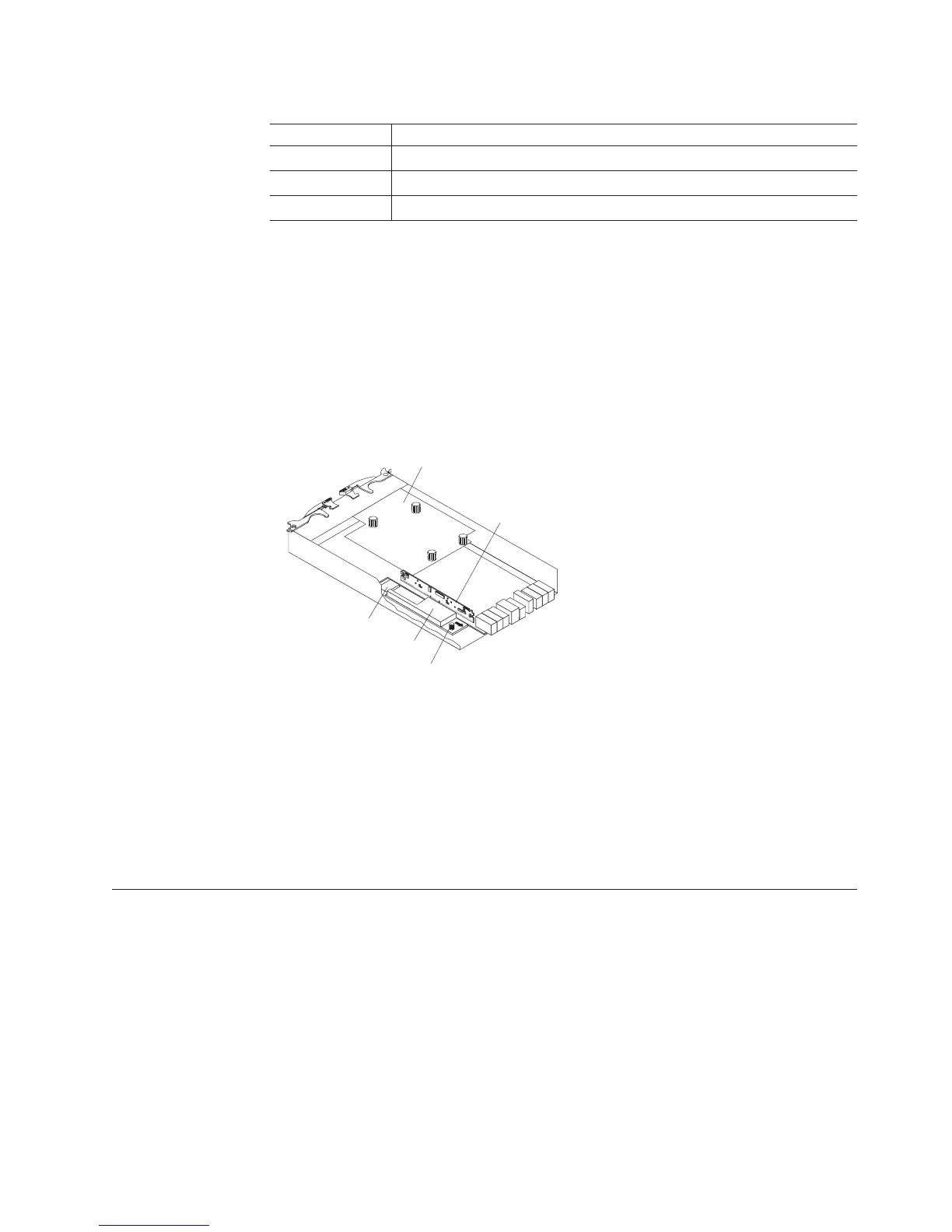
Figure 12 shows the locations of the battery and memory cache DIMM in the
controller.
The battery chargers in the power supplies perform a battery learn test when the
storage subsystem is started for the first time and at a scheduled interval
thereafter. Data caching starts after the battery tests are completed.
The condition of the battery is indicated by an LED on the rear of the controller
(see “Controller LEDs” on page 90 for the location of the battery fault LED and
conditions that the LED indicates). You can also check the status of the battery
using the Storage Manager client software.
Software and hardware compatibility and upgrades
The latest controller firmware, NVSRAM firmware, ESM firmware, and drive
firmware must be installed to ensure optimal functionality, manageability, and
reliability.
Software and firmware support code upgrades
To enable support for the DS3500 storage subsystem, you must ensure that the
system software and firmware are of the latest versions. To find the latest Storage
Manager software, controller firmware, NVSRAM, ESM firmware, and drive
firmware, check the firmware readme files.
Battery connector
Captive fastener
Memory cache battery
Memory
cache DIMM
Host adapter
or filler panel
Figure 12. Battery unit
Chapter 1. Introduction 15