2. Using the supplied strap, tie the dc power supply cable to the rail to provide
strain relief for the power cable.
Note: The supplied dc power cable uses 10 AWG copper conductors.
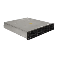
3. Connect the dc power cable to the power supply. See Figure 73 for the dc
power supply connector PIN positions.
Table 13. DC power supply connector - pin descriptions
Number Function DC power cable wire color
1 Pin 1: - 48 V dc Brown
2 Pin 2: POS RTN Blue
3 Pin 3: GND Green/yellow
4. Connect the - 48V wire (brown) of the dc power cable to an approved
disconnect device (circuit breaker) rated at 20 A. The disconnect device must be
easily accessible from the back of the DS3500 unit.
Attention:
v The disconnect device (circuit breaker) must be rated at 20 A. Ensure that at
least 12 AWG or larger copper conductor wires are used for all of the wiring
between the DS3500 or EXP3500 dc power connectors and the dc power
source.
v
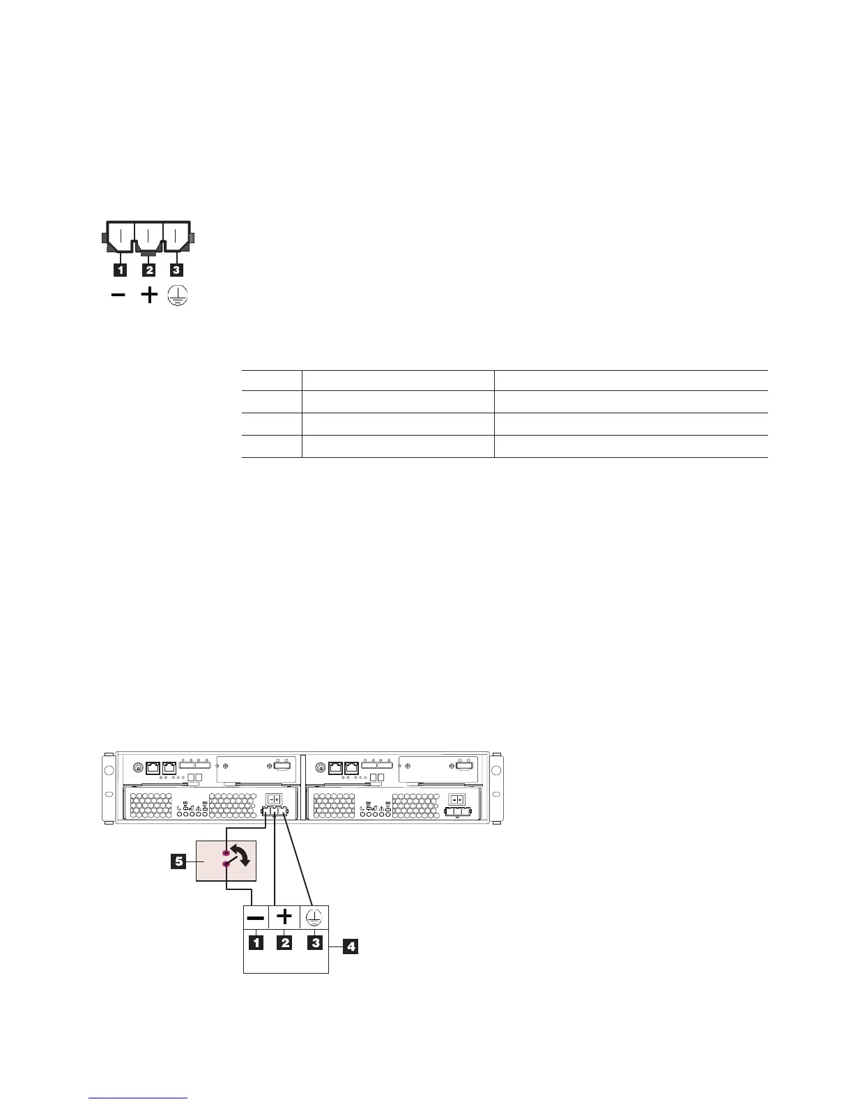
5. Complete the wiring from the disconnect device to the terminal marked -48V of
the Reliably grounded safety extra low voltage (SELV) dc power source.
Connect the POS RTN wire (blue) and the ground wire (green/yellow) of the
dc power cable to the terminals marked POS RTN and GND on the dc power
source, as shown in Figure 74.
Figure 73. DC power connector - pin positions
Figure 74. DC wiring from DS3500 to disconnect device and dc power source
Chapter 3. Cabling the storage subsystem and storage enclosure 79