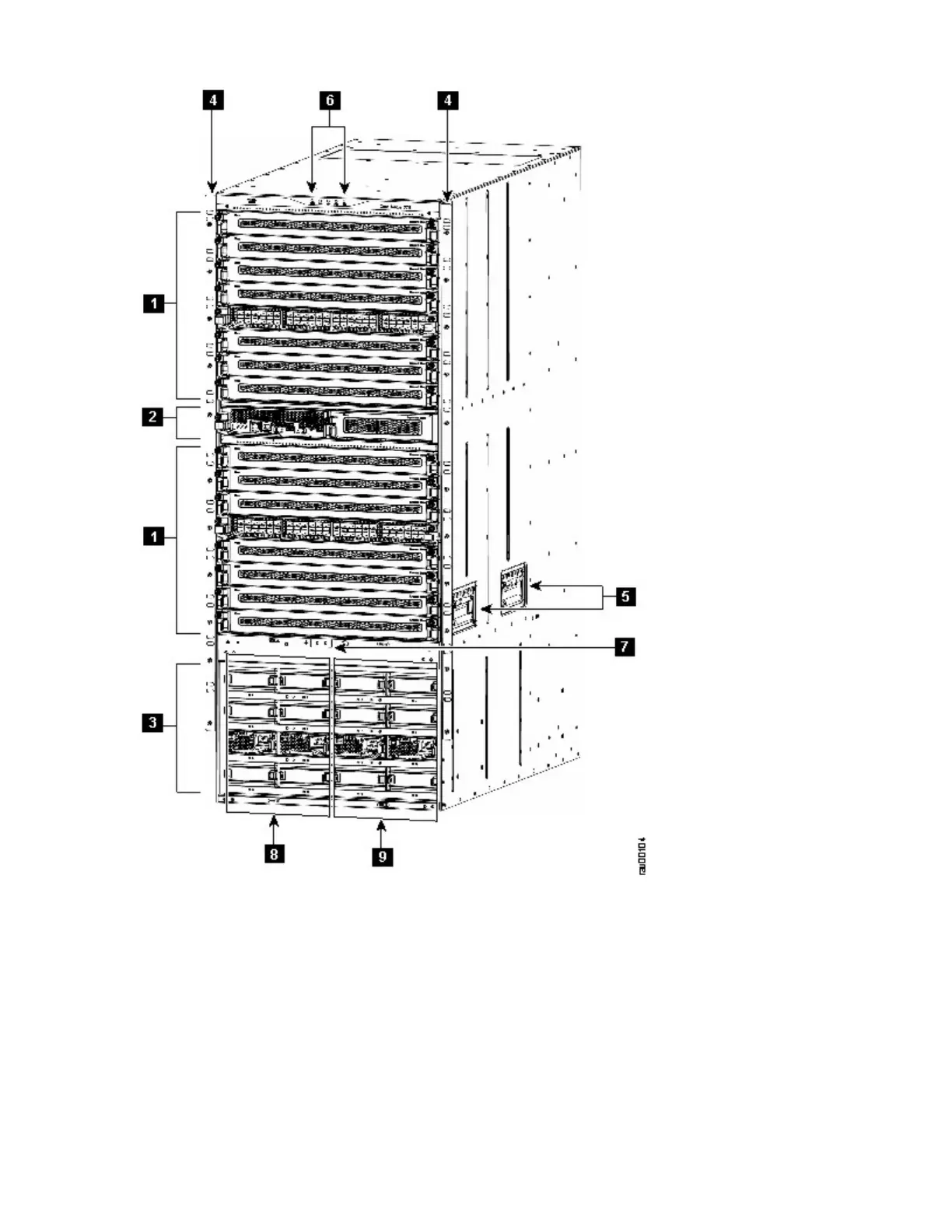
Figure 1. SAN768C-6 Chassis Front View
1. I/O modules (slots 1-8 and 11-18 from top to bottom)
2. Supervisor modules in slots 9 and 10 from left to right
3. Power supply unit bays numbered 1-16 starting from the top left and increasing from left to right and
top to bottom
• The top row has bays 1-4, numbered left to right.
• The second row has bays 5-8, numbered left to the right.
• The third row has bays 9-12, numbered left to the right.
• The fourth row has bays 13-16, numbered left to the right.
Chapter 1. Introducing the IBM c-type SAN Directors5

 Loading...


