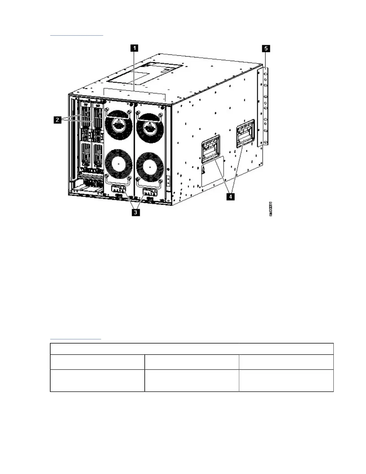
Figure 6 on page 11 shows the rear view of the SAN192C-6 chassis.
Figure 6. SAN192C-6 Chassis Rear View
1. Fan modules - (Three fan modules) 1-3 are numbered left to the right. When the fan modules are
installed, they cover the crossbar fabric switching modules. Only two fan modules are shown in the
figure. One fan module is removed to show the crossbar fabric switching module in back.
2. Crossbar modules - (up to six crossbar fabric switching modules with two modules behind each fan
module). The crossbar fabric switching modules 1 and 2 are behind the fan module slot 1, modules 3
and 4 are behind the fan module slot 2, and modules 5 and 6 are behind the fan module slot 3.
3. LEDs for fan module and crossbar switching fabric modules
4. Handles used for adjusting the chassis placement
5. Vertical mounting brackets
System LEDs
Table 2 on page 11 describes the System LEDs for the IBM c-type SAN directors.
LED Status Description
PSU Green Power supply units are
operational.
Table 2. IBM c-type SAN switches and directors System LEDs
Chapter 1. Introducing the IBM c-type SAN Directors11

 Loading...


