9. If needed, reconnect the power cables to the expansion enclosure, as described in “Powering on the
optional 2076-92F expansion enclosures” on page 112.
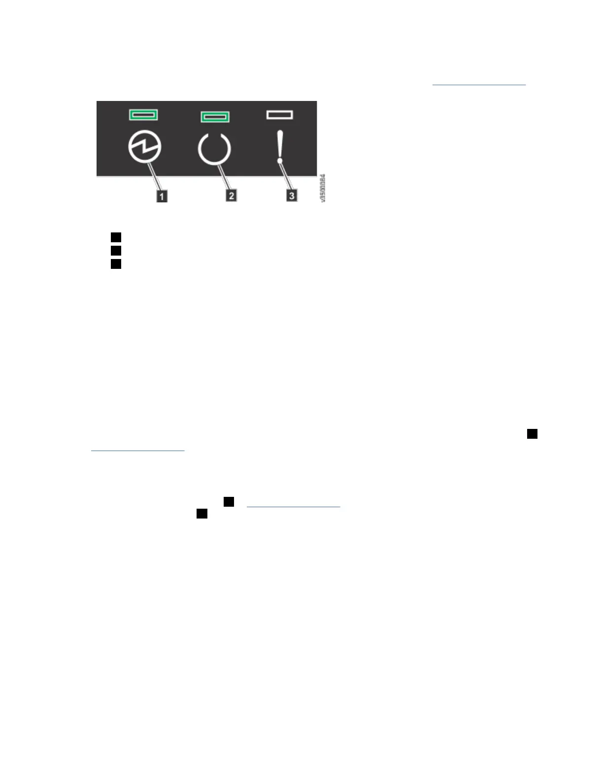
10. Check the LEDs on the top of the secondary expander module to verify that it is receiving power.
“ Storwize V7000 2076-92F expansion enclosure LEDs and indicators” on page 116 describes the
status indicated by the LEDs.
Installing or replacing the fascia: 2076-92F
During the initial installation process or after you perform service, you can install the fascia components
on the front of a 2076-92F expansion enclosure.
About this task
The 4U fascia covers the display panel of the expansion enclosure. It is attached to the enclosure by four
screws. The bottom 1U fascia covers both of the power supply units (PSUs) on the enclosure. As Figure
79 on page 70 shows, the fascias are independent; you can remove or replace one without having to
remove or replace the other.
Figure 79. Fascia components on the expansion enclosure
Note: When the expansion enclosure is shipped, the 4U and 1U fascia are not installed. You must install
them as part of the initial installation process.
Procedure
Attach the front (4U) fascia
1. Align the front 4U fascia with the enclosure so that the thumbscrews go through the holes on each
side. As Figure 80 on page 71 shows, this action aligns the screw holes on the back of the fascia with
the screw holes on the front flange of the enclosure.
2. Replace the four screws to reattach the 4U fascia. Secure the screws from the back of the flange and
into the rear of the fascia. Each side of the 4U fascia contains two screws.
Attach the bottom (1U) fascia
70
Storwize V7000 : Gen3 Quick Installation Guide for MTM 2076-724, 2076-U7B, 2076-12F, 2076-24F, and
2076-92F

 Loading...


