3. Reattach the bottom 1U fascia that covers the power supply units (PSUs). Align the fascia with the
enclosure and gently push it until it clicks into place on the chassis, as shown in Figure 80 on page
71.
Align the tab on each side of the 1U fascia with the corresponding slots on the enclosure flange. Pins
on each flange must also align with a hole in each side of the 1U fascia.
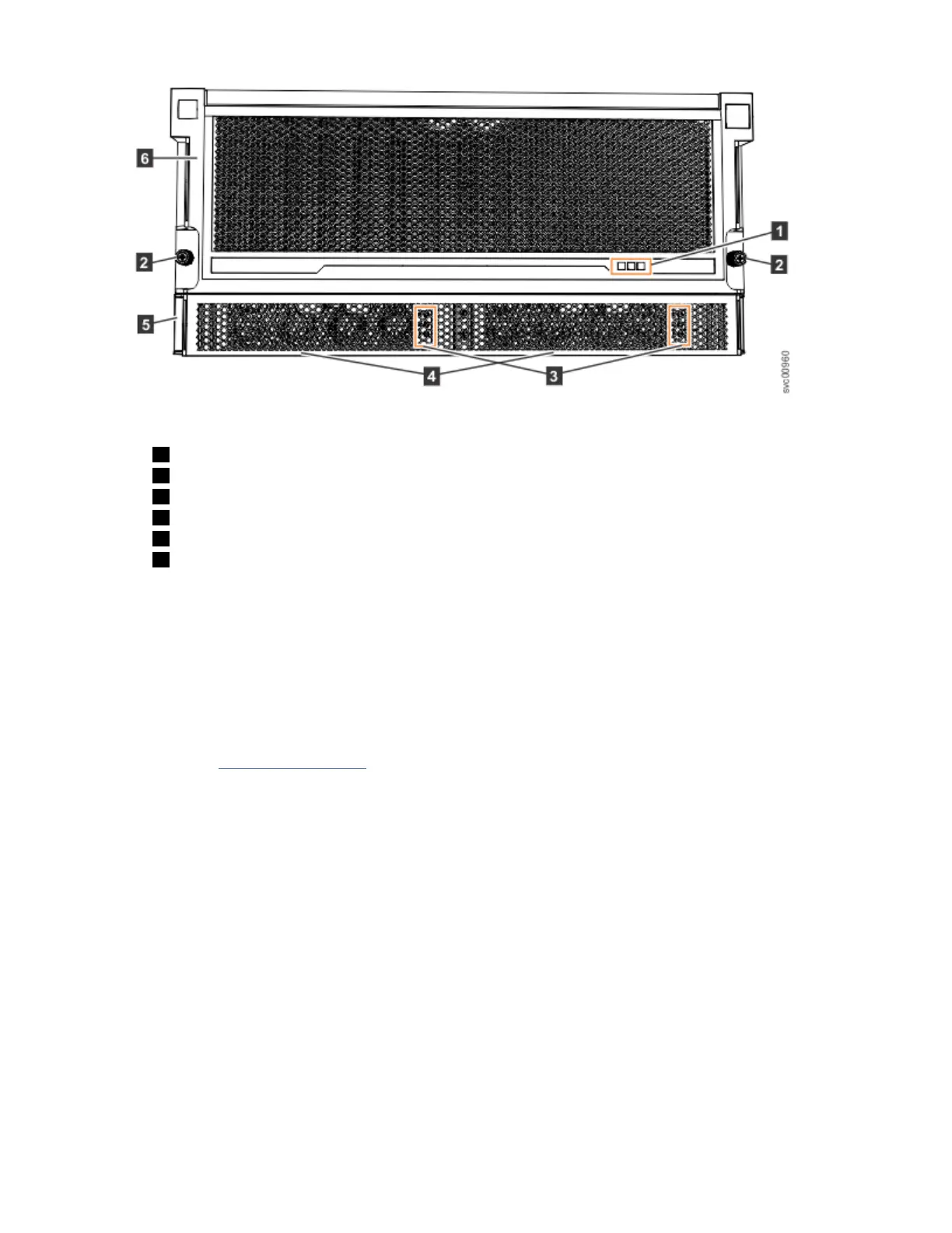
Figure 80. Replace fascia components on the expansion enclosure
Installing or replacing a power supply: 2076-92F
Use the following procedures to replace either of the redundant power supplies in the 2076-92F
expansion enclosure. The redundant power supplies operate in parallel; one continues to provide power
to the enclosure if the other fails.
Before you begin
Important: You can replace a PSU without powering off the expansion enclosure. However, to maintain
operating temperature, replace the PSU within 10 minutes of its removal. When a PSU is removed, the
reduction in airflow through the enclosure might cause the enclosure or its components to shut down to
protect from overheating.
Chapter 2. Installing the system hardware
71

 Loading...


