2 Cable management arm
3 Fascia
Other parts, such as the cover, secondary expander modules, and fans, are installed in the enclosure.
However, due to weight considerations, you must remove some parts and then reinstall them as part of
the initial installation process.
Note: Drives are not included in installation package for the enclosure; they are provided in a separate
package.
Procedure
1. Remove the cardboard tray that contains the slide rails, cable management arm, and fascia from
cardboard box in which the expansion enclosure was shipped.
2. Remove the foam end pieces from the top of the 2076-92F expansion enclosure.
3. Cut the corners of the shipping box and fold them down to uncover the sides and faces of the
expansion enclosure, as shown in Figure 39 on page 44.
Figure 39. Packaging materials
1 Enclosure
2 Top of shipping box, folded back.
3 Foam protectors
4. Remove the top cover, as described in “Removing the top cover: 2076-92F ” on page 46.
5. With two or more persons, push the expansion enclosure sideways onto an adjacent flat bed lift.
Keep the remaining foam block protectors attached to the enclosure.
6. Remove the support rail kit from the box in which it was shipped ( 1 , as shown in Figure 38 on page
43).
7. Separate the inner section of the support rails and attach them to each side of the expansion
enclosure, as described in steps “3” on page 27 through “5” on page 27 in “Installing the support
rails: 2076-92F ” on page 26.
8. Attach the remaining sections of the support rails to the rack, as described in step “6” on page 28 in
“Installing the support rails: 2076-92F ” on page 26.
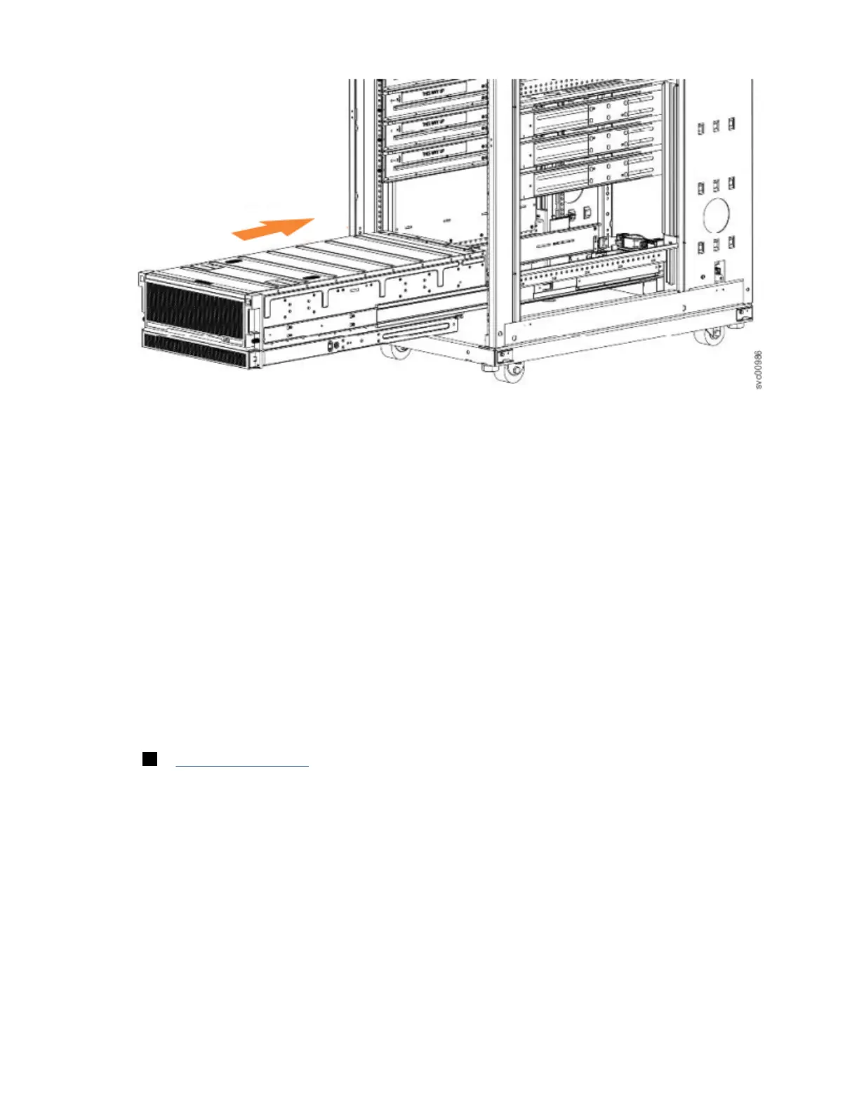
9. Move the mechanical lift to the front of the rack. Align the inner section of the rails with the mid
section of the rails that are extending from the rack.
44
Storwize V7000 : Gen3 Quick Installation Guide for MTM 2076-724, 2076-U7B, 2076-12F, 2076-24F, and
2076-92F
 Loading...


