Figure 33. Features on the front of the 2076-92F expansion enclosure
1 Display panel indicators
2 Rack retention thumb screws
3 Power supply unit indicators
4 Power supply units (PSUs)
5 PSU fascia (1U)
6 Front fascia (4U)
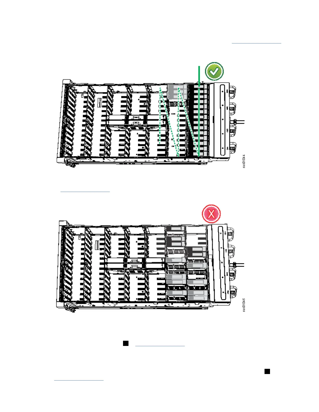
However, as Figure 34 on page 40 shows, the 4U and 1U fascias are packaged separately. You must
attach them to the front of the 2076-92F expansion enclosure as part of the initial installation process.
Figure 34. Front fascia of the 2076-92F expansion enclosure
40
Storwize V7000 : Gen3 Quick Installation Guide for MTM 2076-724, 2076-U7B, 2076-12F, 2076-24F, and
2076-92F
 Loading...


