Installing the support rails: 2076-92F
You must install the support rails before you can install a 2076-92F expansion enclosure in a rack.
Procedure
1. Locate the hardware that is used to install the rails, including the M4xL6 and M5xL13 screws.
Set the hardware, which is shown in Figure 43 on page 47, aside for use later in the installation
process.
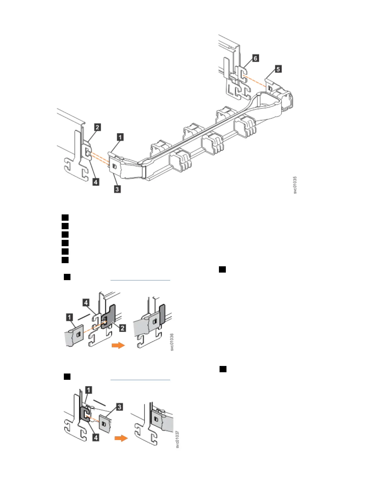
Figure 43. Support rails
2. Select an available 5U space in your rack to install the expansion enclosure.
Important notes:
• When you select a rack location, ensure that the enclosure and its parts are easily accessible. Allow
enough space for the lid to be easily removed and for internal components, such as drives and
secondary expansion modules, to be serviced.
• When all components and drives are installed, the expansion enclosure is heavy. Install the support
rails and enclosure at the lowest available position. Do not install the rails and enclosure above
position U25 in the rack.
3. Remove the inner member of the rail. Push the tab ( a ) and slide the middle rail member back, as
shown in Figure 44 on page 48.
Chapter 2. Installing the system hardware
47
 Loading...


