Table 11. Weight of an enclosure with 92 SAS drives
FRU description
Approximate weigh per unit
Maximum
supported
Approximate extra weight
kg lb kg lb
2.5-inch tier 0
flash drive
2.5-inch tier 1
flash drive
0.224 0.494 92 20.608 45.433
2.5-inch hard
disk drive
0.304 0.670 92 27.968 61.659
3.5-inch Near-
Line SAS hard
disk drive
0.876 1.931 92 80.592 177.675
As you install or replace FRUs, the overall weight of the expansion enclosure increases. For example,
Table 12 on page 37 shows the weight progression as different combinations of FRUs are installed.
Table 12. Enclosure weight as FRUs are installed
Enclosure assembly Approximate weight
FRUs installed FRUs not installed kg lb
• Enclosure (01LJ607 or
01LJ112)
• Secondary expansion
modules
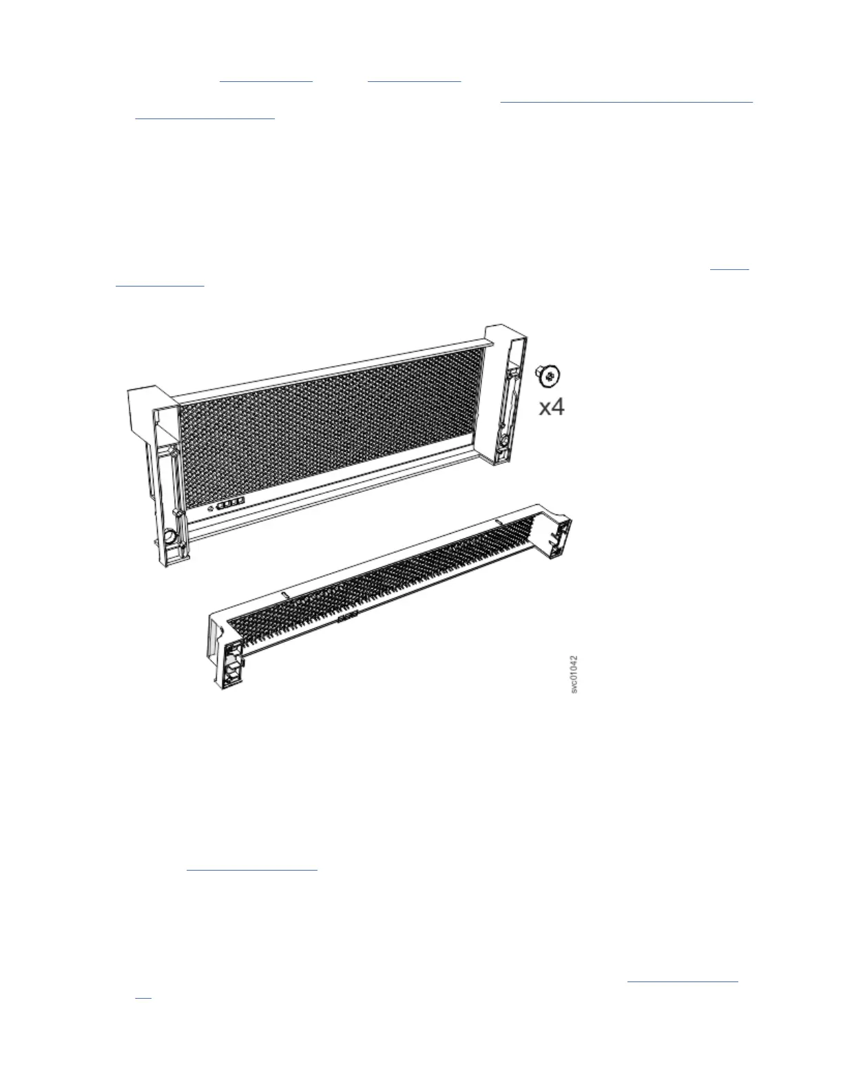
• Fascia (1U and 4U)
• PSUs
• Expansion canisters
• Fan modules
• Fan interface board
• Display assembly
• Drives
• Cover
42.5 93.7
• Enclosure (01LJ607 or
01LJ112)
• Secondary expansion
modules
• Fascia (1U and 4U)
• PSUs
• Expansion canisters
• Fan modules
• Fan interface board
• Display assembly
• Drives
• Cover
44.3 97.7
Chapter 2. Installing the system hardware 37

 Loading...


