5. Move the UEFI boot backup jumper (J15) from pins 1 and 2 to pins 2 and 3 to
enable the UEFI recovery mode.
6. Reinstall the server cover; then, reconnect all power cords.
7. Restart the server. The system begins the power-on self-test (POST).
8. Boot the server to an operating system that is supported by the firmware
update package that you downloaded.
9. Perform the firmware update by following the instructions that are in the
firmware update package readme file.
10. Turn off the server and disconnect all power cords and external cables, and
then remove the cover (see “Removing the top cover” on page 146).
11. Move the UEFI boot backup jumper (J15) from pins 2 and 3 back to the
primary position (pins 1 and 2).
12. Reinstall the cover (see “Replacing the top cover” on page 147).
13. Reconnect the power cord and any cables that you removed.
14. Restart the server. The system begins the power-on self-test (POST). If this
does not recover the primary bank, continue with the following steps.
15. Remove the top cover (see “Removing the top cover” on page 146).
16. Reset the CMOS by removing the system battery (see “Removing the system
battery” on page 241).
17. Leave the system battery out of the server for approximately 5 to 15 minutes.
18. Reinstall the system battery (see “Replacing the system battery” on page 243).
19. Reinstall the top cover (see “Replacing the top cover” on page 147).
20. Reconnect the power cord and any cables that you removed.
21. Restart the server. The system begins the power-on self-test (POST).
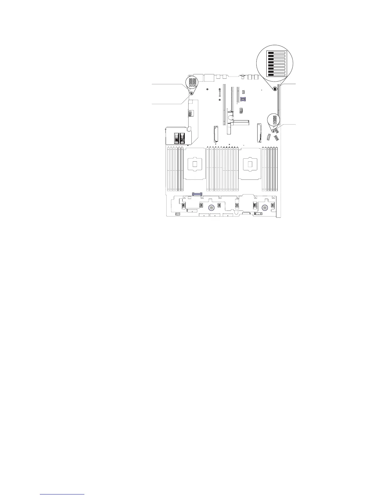
System TPM physical
presence jumper
CMOS clear jumper
UEFI boot backup jumper
Switch block 6 (SW6)
Figure 46. UEFI boot backup jumper (J15) location
118 System x3650 M5 Type 5462: Installation and Service Guide
 Loading...


