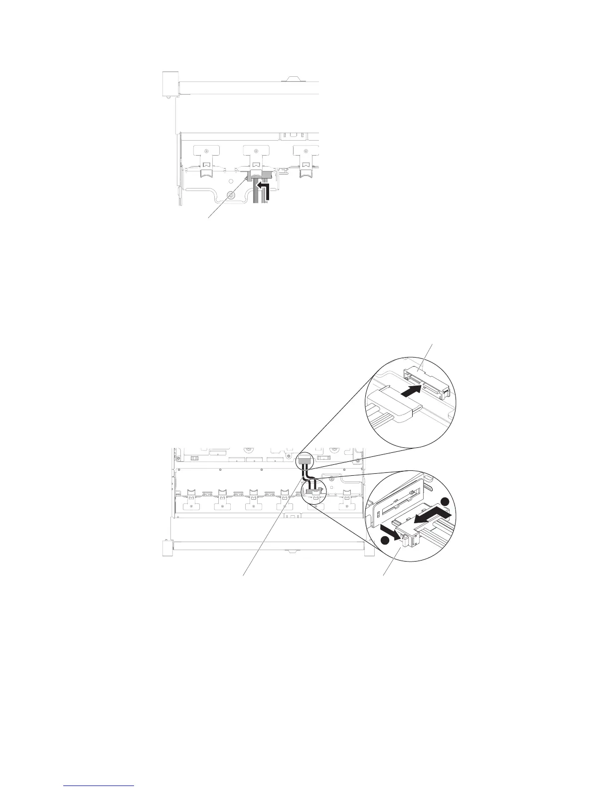
The following illustration shows cable routing for the optical cable:
Attention: Follow the optical drive cable routing as the illustration shows.
Make sure that the cable is not pinched and does not cover any connectors or
obstruct any components on the system board.
6. Replace the fan cage assembly (see “Replacing the fan cage assembly” on page
173).
7. Replace the top cover (see “Replacing the top cover” on page 147).
8. Slide the server into the rack.
9. Reconnect the power cords and any cables that you removed.
10. Turn on the peripheral devices and the server.
Cable connector latch
Figure 87. Optical drive cable latch
DVD drive cable
Cable connector latch
Optical drive
connector
2
Figure 88. Optical drive cable routing
162 System x3650 M5 Type 5462: Installation and Service Guide
 Loading...


