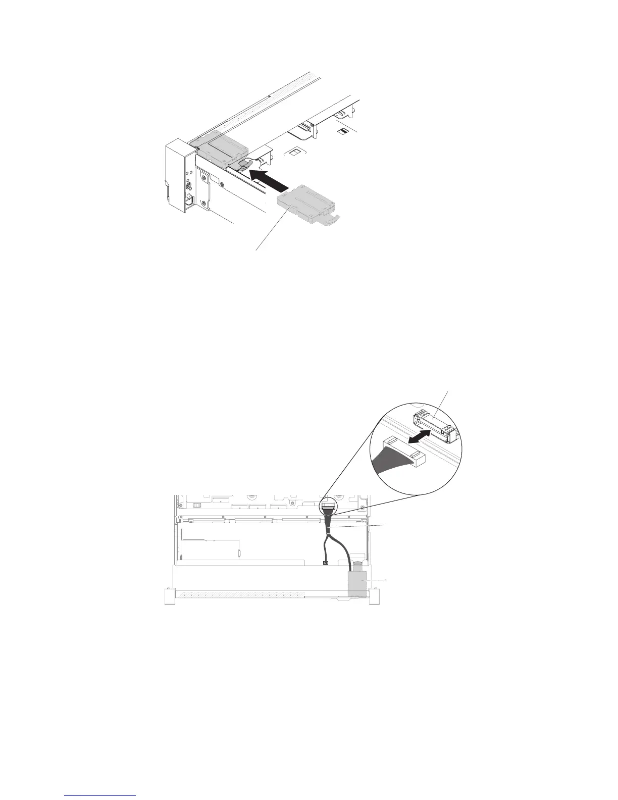
5. Inside the server, connect the operator information panel assembly cable to the
system board.
The following illustration shows the cable routing for the operator information
panel.
Note: To connect the operator information panel cable on the system board,
press evenly on the cable. Pressing on one side of the cable might cause
damage to the cable or connector.
6. Replace the top cover (see “Replacing the top cover” on page 147).
7. Slide the server into the rack.
8. Reconnect the power cords and any cables that you removed.
9. Turn on the peripheral devices and the server.
Operator information
panel assembly
Figure 211. Operator information panel installation
Operator information /
LCD panel connector
Operator information /
LCD panel cable
Operator information
panel assembly
Figure 212. Operator information panel cable routing
256 System x3650 M5 Type 5462: Installation and Service Guide
 Loading...


