5. To obtain more working room, remove the fan cage (see “Removing the fan
cage assembly” on page 172).
6. Pull the hard disk drives or fillers out of the server slightly to disengage them
from the backplanes. For more information, (see “Removing a hot-swap hard
disk drive” on page 154).
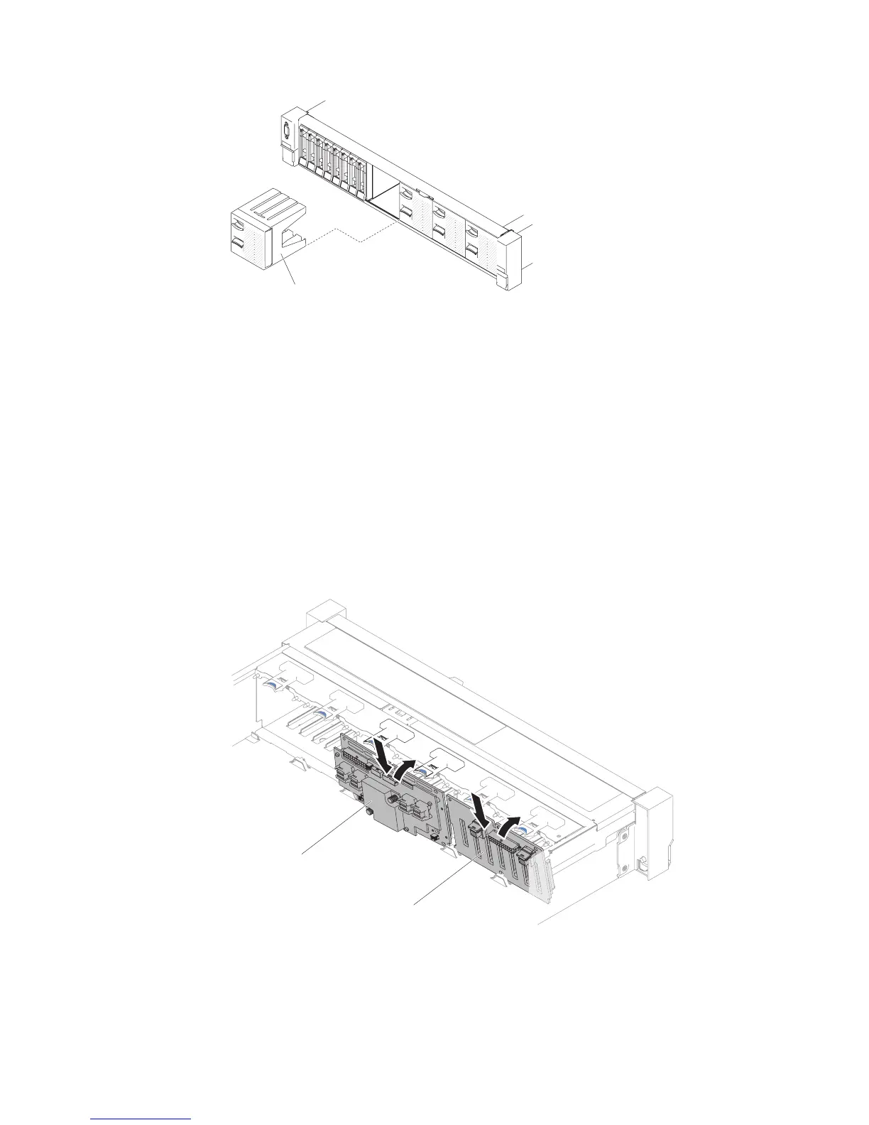
7. Install the new backplane in slot 2 or slot 3 depending on your configuration.
Insert the backplane tabs into slots on the bottom of the cage and push the
backplane forward into the release latch (on top of the backplane cage) until
the backplane is locked in place.
Note: You can connect the cables to the drive backplane before installing the
backplane onto the cage or you can connect the cables after you install the
backplane, if that is easier for you.
8. Connect SAS signal and power/configuration cables to the backplane and the
system board as the following illustrations.
v If the new backplane is installed in slot 2, route cables as the following
illustration.
4-drive filler panel
Figure 249. Filler panels
2.5-inch HDD hot-swap backplane
2.5-inch HDD hot-swap
backplane (expander)
Figure 250. Backplane installation
292 System x3650 M5 Type 5462: Installation and Service Guide
 Loading...


