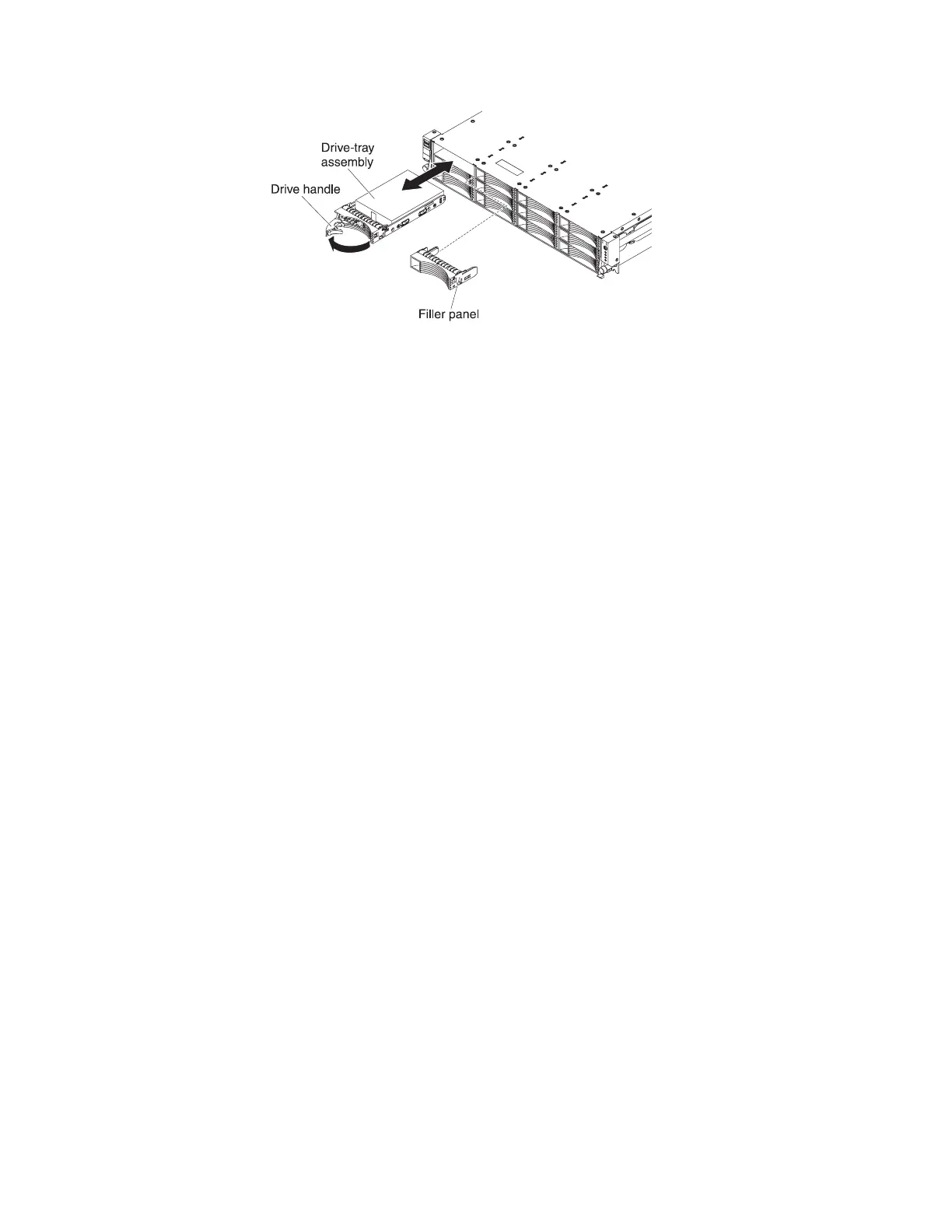
To install a drive in a hot-swap bay, complete the following steps.
Attention: To maintain proper system cooling, do not operate the server for more
than 10 minutes without either a drive or a filler panel installed in each bay.
1. Orient the drive as shown in the illustration.
2. Make sure that the tray handle is open.
3. Align the drive assembly with the guide rails in the bay.
4. Gently push the drive assembly into the bay until the drive stops.
5. Push the tray handle to the closed (locked) position.
6. If the system is turned on, check the hard disk drive status LED to verify that
the hard disk drive is operating correctly.
After you replace a failed hard disk drive, the green activity LED flashes as the disk
spins up. The amber LED turns off after approximately 1 minute. If the new drive
starts to rebuild, the amber LED flashes slowly, and the green activity LED remains
lit during the rebuild process. If the amber LED remains lit, see “Hard disk drive
problems” on page 40.
Note: You might have to reconfigure the disk arrays after you install hard disk
drives. See the RAID documentation on the IBM ServeRAID Support CD for
information about RAID controllers.
Removing a hot-swap power supply
Important: If the server has two power supplies, and if you remove either of them,
the server will not have redundant power; if the server power load then exceeds
675 W, the server might not start or might not function correctly.
To remove a power supply, complete the following steps.
1. Read the safety information that begins on page vii and “Installation guidelines”
on page 133.
2. If only one power supply is installed, turn off the server and peripheral devices.
3. Disconnect the power cord from the power supply that you are removing.
4. Grasp the power-supply handle.
5. Press the orange release latch to the left and hold it in place.
Chapter 5. Removing and replacing server components 139
 Loading...