EasyManuals Logo

IBM x3630 M3 7377 User Manual

IBM x3630 M3 7377
294 pages
To Next Page IconTo Next Page
To Previous Page IconTo Previous Page
Page #203 background imageLoading...
Page #203 background image
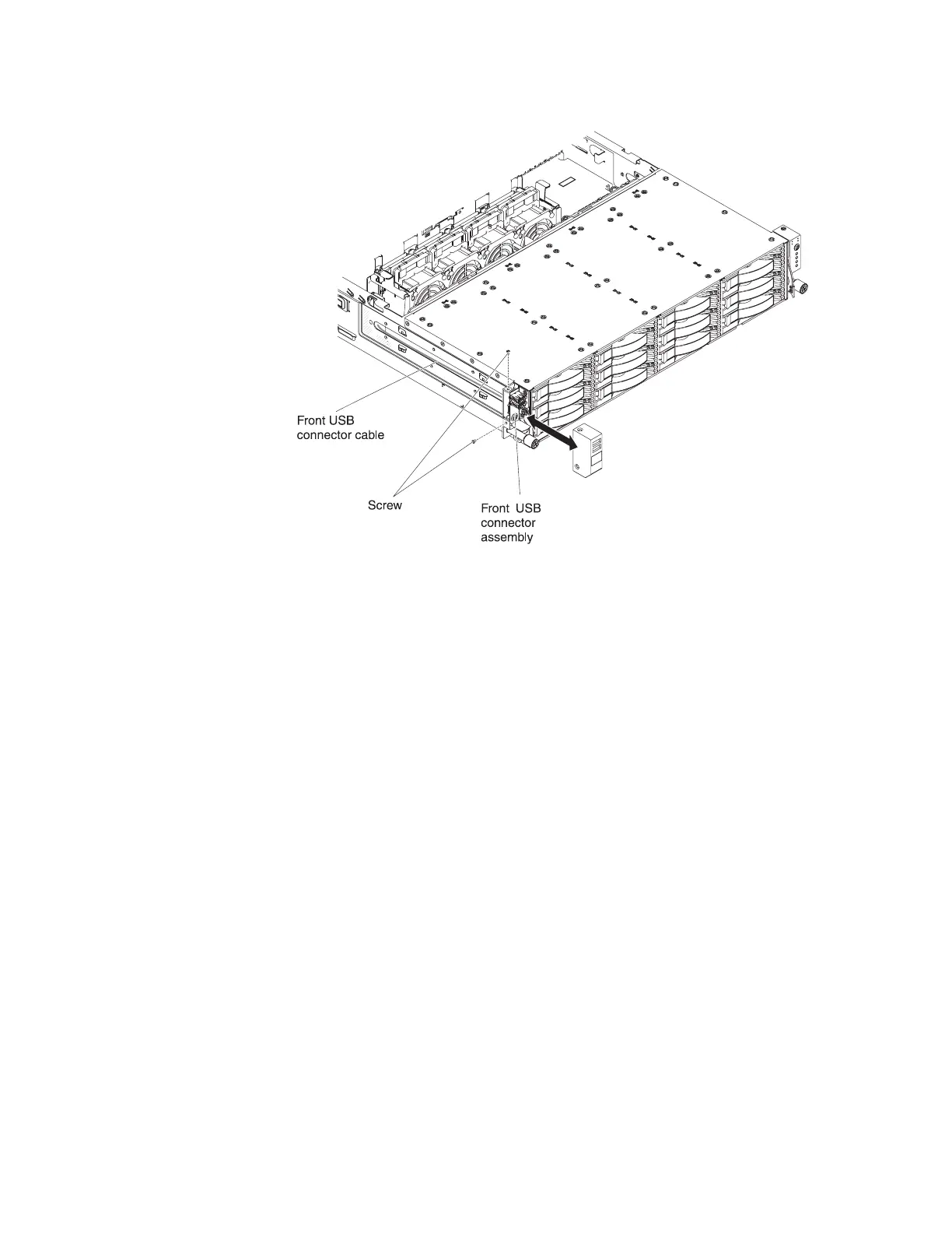
2. Reconnect the cable to the front USB connector assembly.
3. Place the front USB connector assembly in the bracket cover. Make sure it is
securely seated inside the bracket cover.
4. Install the screws to secure the bracket cover to the server.
5. Connect the cable to the USB board. The following illustration shows the
internal cable routing and connector for the USB cable.
Note: The cable is routed on the outside of the chassis and connected to the
USB connector board. The cable must be protected by the cable cover on the
side of the chassis.
Chapter 5. Removing and replacing server components 185

Table of Contents

Questions and Answers:

Question and Answer IconNeed help?

Do you have a question about the IBM x3630 M3 7377 and is the answer not in the manual?

IBM x3630 M3 7377 Specifications

General IconGeneral
Product FamilySystem x
Machine Type7377
Max Processors2
ChipsetIntel 5520
Memory Slots12 DIMM slots
ProcessorIntel Xeon 5600 series
MemoryUp to 192 GB
RAID SupportRAID 0, 1, 10, 5, 50
Network Interface2 x Gigabit Ethernet
Power SupplyHot-swap, redundant
Operating System SupportMicrosoft Windows Server, Red Hat Enterprise Linux, SUSE Linux Enterprise Server, VMware

Related product manuals