1-33
ROCKY-6614 CPU Card
33
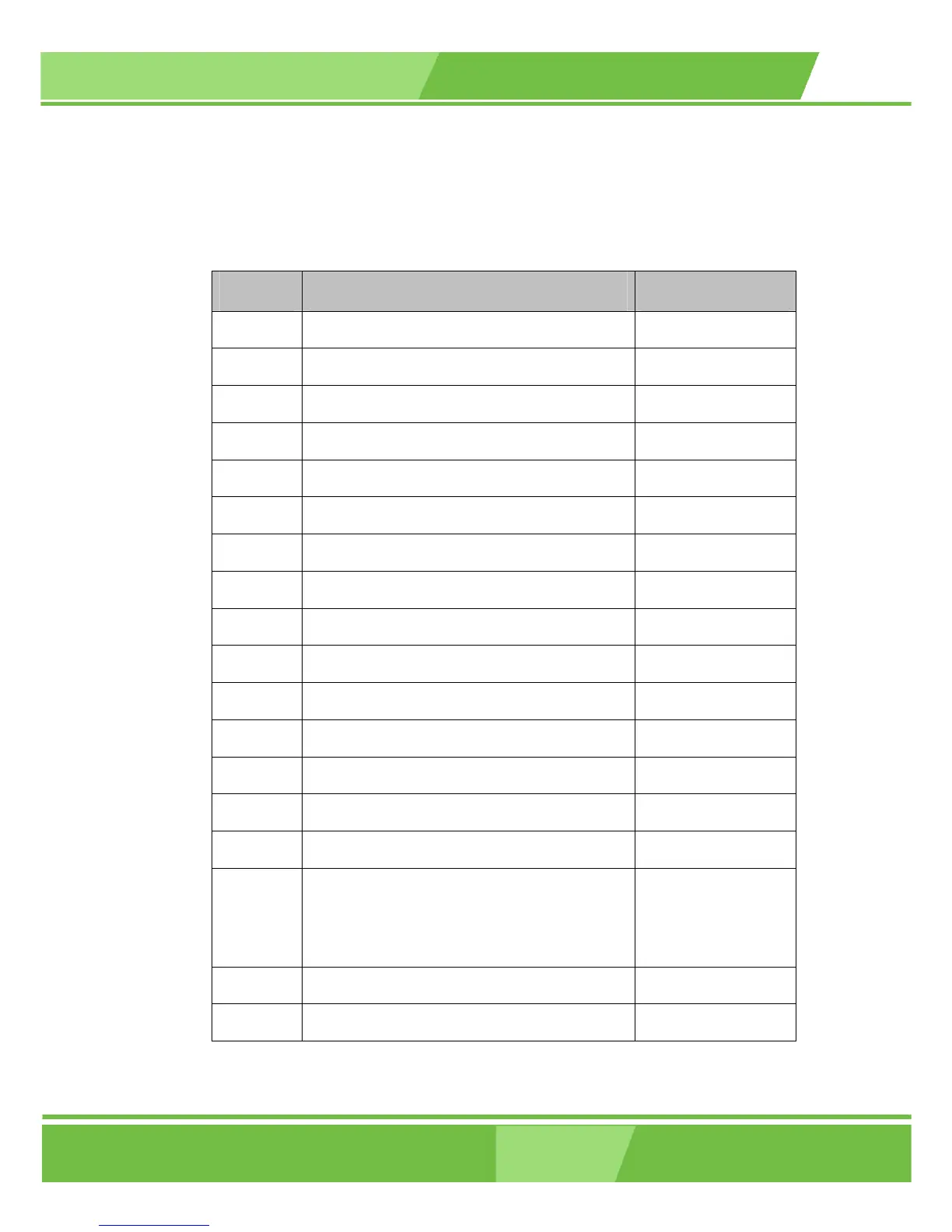
3.1.2 Peripheral Interface Connectors
Table 3-1 shows a list of the peripheral interface connectors on the ROCKY-6614 CPU
board. Detailed descriptions of these connectors can be found in Section 3.2 on page 35.
Label Connector Type
FDD1 FDD connector 34-pin header
PIDE1 Primary HDD connector 40-pin header
SIDE1 Secondary HDD connector 40-pin header
COM1 Serial communications connector 5-pin header
COM2 Serial communications connector 5-pin header
LPT1 Parallel port connector 26-pin header
SATA 1 SATA drive port (150MB/s) SATA disk drive port
SATA 2 SATA drive port (150MB/s) SATA disk drive port
DIO1 Digital Input Output connector 10-pin header
CPU12V1 ATX 12V connector 4-pin header
CPU_FAN1 CPU cooling fan connector 3-pin header
USB23 USB connector for 2 USB devices 8-pin header
USB45 USB connector for 2 USB devices 8-pin header
USB67 USB connector for 2 USB devices 8-pin header
IR1 Infrared 5-pin header
F_PANEL1 Front Panel connector connects to chassis
front panel power and reset buttons as status
LEDs
12-pin header
ATXCTL1 Connects the CPU board to the backplane 3-pin header
LINE_IN1 4-pin header
 Loading...


