1-53
ROCKY-6614 CPU Card
53
One 1Gb connections can be made between the Ethernet connector and a Local Area
Network (LAN) through a network hub. An RJ-45 Ethernet connector is shown in Figure
3-16.
PIN
DESCRIPTION PIN DESCRIPTION
1 TXD+ 8 GND
2 TXD- 9
GRN+
3 RXD+ 10
GRN-
4 CT_TXD 11 YEL-
5 CT_RXD 12
YEL+
6 RXD- 13
S GND
7 N/C 14 S GND
Table 3-18: RJ-45 Ethernet Connector Pinouts
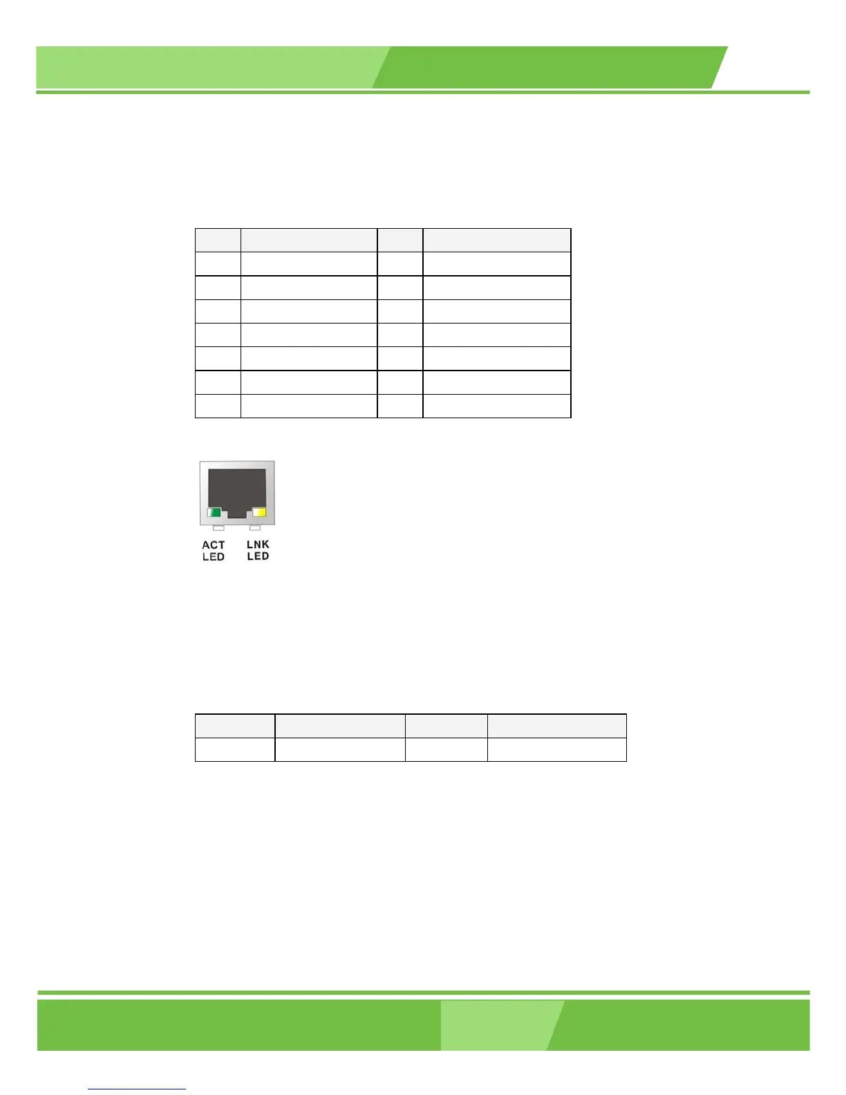
Figure 3-16: RJ-45 Ethernet Connector
The RJ-45 Ethernet connector has two status LEDs, one green and one yellow. The green
LED indicates activity on the port and the yellow LED indicates the port is linked. See Table
3-19.
STATUS
DESCRIPTION STATUS DESCRIPTION
GREEN Activity YELLOW Linked
Table 3-19: RJ-45 Ethernet Connector LEDs
3.3.4 VGA Connector
CN Label: VGA1
CN Type: 15-pin
CN Location: See Figure 3-14 (labeled number 7)
 Loading...


