1-51
ROCKY-6614 CPU Card
51
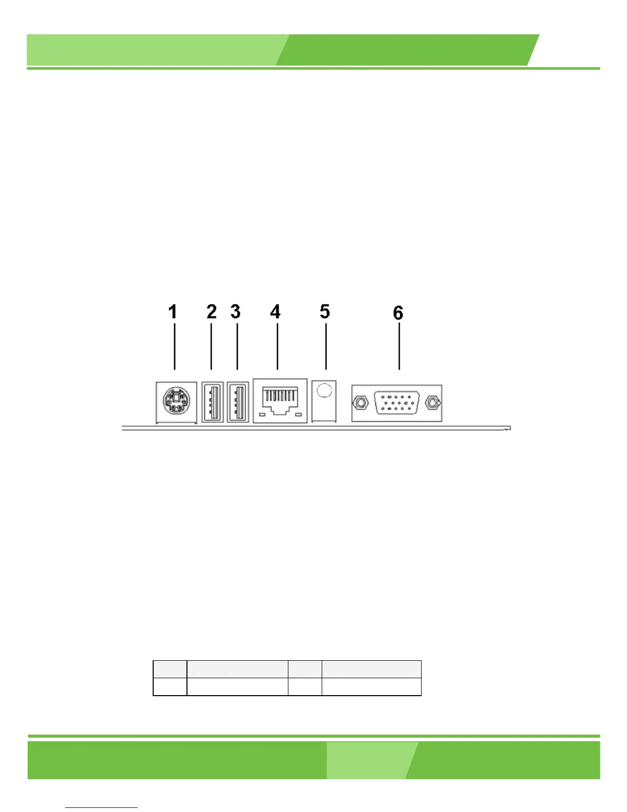
3.3 External (Rear Panel) Connectors
Figure 3-14 shows the ROCKY-6614 CPU board rear panel. The peripheral connectors on
the back panel can be connected to devices externally when the CPU card is installed in a
chassis. The peripheral connectors on the rear panel are:
1 x PS/2 keyboard connector
2 x USB connectors
1 x RJ-45 GbE connector
1 x VGA connector
1 x Line-out connector
Figure 3-14: ROCKY-6614 CPU Board Rear Panel
3.3.1 PS/2 Connector
CN Label: KB_MS1
CN Type: PS/2
CN Location: See Figure 3-14 (labeled number 1)
CN Pinouts: See Table 3-16
Figure 3-15 shows PS/2 Pinout locations
The PS/2 mouse and keyboard connectors are connected to a mouse and keyboard
PIN DESCRIPTION PIN DESCRIPTION
1 KB Data 2 N/C
 Loading...


