1-35
ROCKY-6614 CPU Card
35
3.2 Internal Peripheral Connectors
Internal peripheral connectors are found on the CPU card and are only accessible when
the CPU board is outside of the chassis. This section has complete descriptions of all the
internal, peripheral connectors on the ROCKY-6614 CPU board.
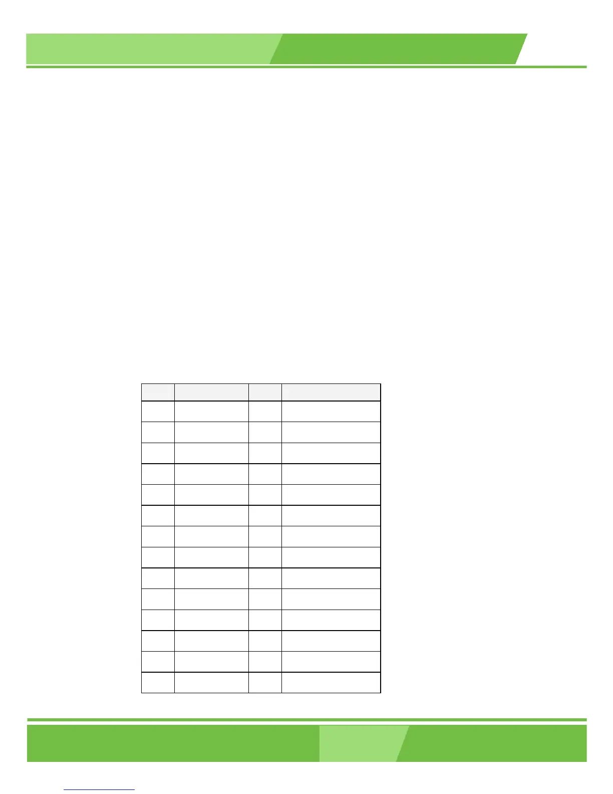
3.2.1 FDD Connector
CN Label: FDD1
CN Type: 2x17 pin header
CN Location: See Figure 3-2
CN Pinouts: See Table 3-4
The ROCKY-6614 is shipped with a 34-pin daisy-chain drive connector cable. This cable
can be connected to the FDD connector.
PIN DESCRIPTION PIN DESCRIPTION
1 GND 2 REDUCE WRITE
3 GND 4 N/C
5 N/C 6 N/C
7 GND 8 INDEX#
9 GND 10 MOTOR ENABLE A#
11 GND 12 DRIVE SELECT B#
13 GND 14 DRIVE SELECT A#
15 GND 16 MOTOR ENABLE B#
17 GND 18 DIRECTION#
19 GND 20 STEP#
21 GND 22 WRITE DATA#
23 GND 24 WRITE GATE#
25 GND 26 TRACK 0#
27 GND 28 WRITE PROTECT#
 Loading...


