1-69
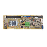
ROCKY-6614 CPU Card
69
4.4 Chassis Installation
After the CPU, the cooling kit, and the DIMM modules have been installed and after the
internal peripheral connectors have been connected to the peripheral devices and the
jumpers have been configure, the CPU Card can be mounted into chassis.
To mount the CPU Card into a chassis please refer to the chassis user guide that came
with the product.
4.5 Rear Panel Connectors
4.5.1 LCD Panel Connection
The conventional CRT monitor connector, VGA1, is a 15-pin, female D-SUB connector.
Pin assignments can be seen in that can be connected to external monitors.
4.5.2 Ethernet Connection
The rear panel RJ-45 connectors can be connected to an external LAN and communicate
with data transfer rates up to 1Gb/s.
4.5.3 USB Connection
The rear panel USB connectors provide easier and quicker access to external USB devices.
The rear panel USB connector is a standard connector and can easily be connected to
other USB devices.
 Loading...
