The connector is also supplied with an adapter to fit a Burton 5506 shellsize 20 type connector
interface. Other adapters can be provided on request.
Note: check all O-rings and O-ring seal surfaces prior to mounting the connector.
Lubricate O-rings with Molykote 1.1.1 or similar.
When installing the canister to a metal frame please note the following:
- As a general rule care must be taken that certain types of different metals are not in
contact with each other in salt water without some type of cathoddic protection.
- The canister should if possible be electrically isolated from the frame to avoid galvanic
corrosion.
- The canister should be connected to an anode bank, typical zinc anodes, on the frame.
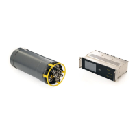
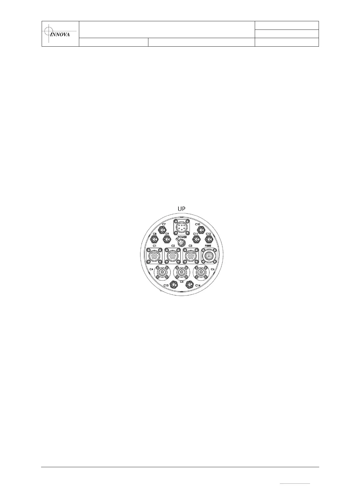
- When mounted horisontally (lying down), the canister must be placed with the correct
side up. This is to ensure functionality of the water detection sensors. Refer to Figure 4
for details.
Figure 4 - Canister orientation
3.2.4 Fibre-optic connection
A fully transparent fibre connection is required between Fibre of the Seacon OPT-F-1 connector
in the subsea canister, and the SC connector in the topside unit.
The fibre optic budget is 26 dB, which is suitable for a typical ROV set-up with 2 slip rings and
3000m umbilical cable. Maximum received power for the fibre transceivers is -9dBm. Transmit
power is typically 0-3 dBm.
Note: If the optical loss through the system is is less than 14dB an attenuator should be added to
the fiber connection to avoid receiver saturation.
Note: When using the OPT-G-4 connector: Fibre 1 in the subsea connector is used for
communication. The remaining fibres are spare. Fibre 1 and 2 are single mode, while fibre 3 and
4 are multi mode.
The system is designed for use with single mode fibre, but can be modified for use with multi
mode fibre, by replacing the CWDMs in the bottle and topside unit.
 Loading...