P.O. BOX 390 Tel.: +47 51 96 17 00 post@innova.no
4067 Stavanger, Norway Fax.: +47 51 96 17 01 www.innova.no
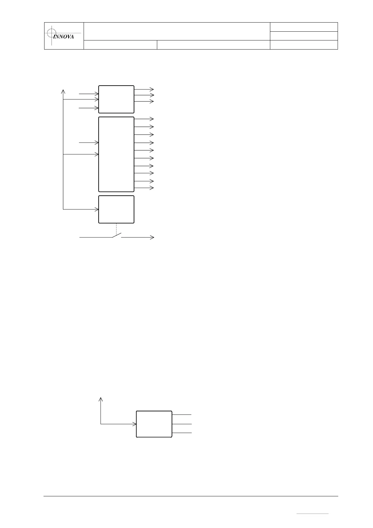
Figure 10 – Power switching overview
5.2.7 Earth Insulation Monitoring & Water Alarm
The Matrix Controller board measures the insulation resistance between the DC power output
and the protective earth. Measurement is done by inserting a low current DC signal on the DC
power output. The measured signal of the insulation measurement board is a voltage signal
proportional to the measured resistance between the DC power system and protective earth.
A water alarm indicates if there is any water intrusion in the canister. The water alarm circuit
measures the resistance between two sets of probe pins located near the lowest level in the
canister. Measurement is taken every 20 s and displayed on the host system.
3ch
Power
Ctrl
10ch
Power
Ctrl
Matrix
Ctrl
RS485
LINK
48Vdc
24Vdc
110VAC
C1 – Multibeam 1
C4 – Serial RS232, Camera 1
C5 – Serial RS232. Camera 2
C6 – Serial RS232, Camera 3
C7 – Serial RS232
C8 – Serial RS232
C9 – Ethernet, TTL
C13 – Serial RS485/RS232
C14 – Serial RS485/RS232
24Vdc
C10 – Serial RS232, 5V TTL
C11 – Serial RS485/RS232
C3 – Multi Interface
C2 – Multibeam 2
C12 – Serial RS232