Innova – Matrix MK II+
Operation and Maintenance Manual
P.O. BOX 390 Tel.: +47 51 96 17 00 post@innova.no
4067 Stavanger, Norway Fax.: +47 51 96 17 01 www.innova.no
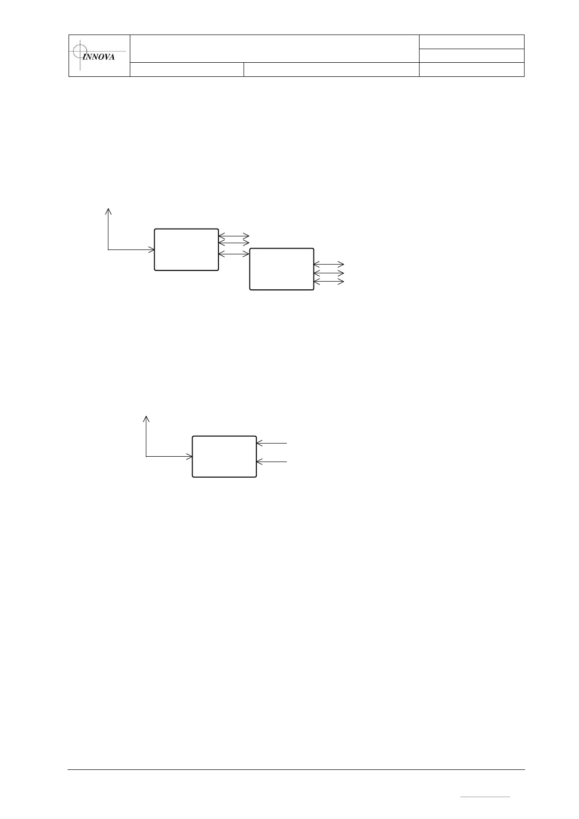
5.2.8 Ethernet channels
The 4 channel Ethernet board connects the subsea Ethernet channels to the topside Ethernet
system. The communication speed on channel 1 to 2 is set to 1Gbps and used for MBE's (C1 &
C2). Channel 3 is set to 1Gbps and connected to a switch which provides 2 100Mbps lines to the
Multi interface connector (C3), and one to C9. Channel 4 is not used.
Ethernet
LINK
Fiber
LINK
C1 – Multibeam 1
C2 – Multibeam 2
(1Gbps)
(1Gbps)
Ch1
Ch2
Ch3
Ch4
Ethernet
Switch
Ch1
Ch2
Ch3
Ch4
(1 Gpbs)
C3 – Multi interface (100Mbps)
C3 – Multi interface (100Mbps)
C9 – Multi interface (100Mbps)
Figure 12 – Ethernet channels overview
5.2.9 PECL channels (optional)
PECL
LINK
Fiber
LINK
C1 – MBE 1
C2 – MBE 2
Ch1 input
Ch1 output
Ch2 input
Ch2 output
Figure 13 – PECL channels overview
The LINK PECL is a two-way board where the Matrix only transmits from the subsea unit an up.
It is used in collaboration with a serial line to control the PECL Multibeam unit. The board can
transmit up to 200Mbps of data per channel.
5.2.10 Serial lines
The Matrix contains 2 serial extension boards, each with 5 off RS232, 2 off RS232/RS485 and 1
off Trigger. The serial extension board is used together with a LINK AV board to provide an
optical link to topside system.
 Loading...