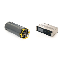
5.2.5 System description
The subsea control bottle is a one-atmospheric canister populated with the following
components:
• LINK Ethernet board
• LINK DV board (optional)
• LINK AV board
• LINK 5 x RS232, 2 x RS232/RS485, 1 x Trigger board
• LINK PECL board (optional)
• Power distribution board - 3 individual outputs
• Power distribution board - 10 individual power outputs
• Matrix controller board
• Power supply
• Power Line input filter
The electronics are mounted inside a rack which is fixed to the end cap. All connectors are
mounted to the end cap, making it easy to slide out the entire assembly for service.
The canister can be fitted to use a fibre penetrator or fibre optic connector for connection of the
fibre optics to the host ROV.
If the option of the Fibre optical connector is chosen, a connector for the host ROV with a 5500-
20XX flange adapter along with a 4m fibre optical cable is included.
5.2.6 Power switching
The output power switching of the 24/48VDC, max 6A outputs are done by the Matrix 3 Ch.
Power Controller board. The 24VDC, max 2V outputs are switched by the 10 Ch. Power
Controller board. The 110/230VAC output is switched by a relay on the Matrix Controller board.
The Matrix 3 Ch. Power Controller has 3 power channels that can select between 2 different
voltages. The channels for the MBE's (C1 & C2) are connected to 24VDC and 48VDC power
supplies so for these connectors one can choose between 24VDC or 48VDC power to the MBE.
The channel used for the Multi interface output (C3) is connected to a dedicated 24VDC power
supply. 6A of 24VDC is available on this connector. If 48VDC is wanted here instead, the
dedicated power supply has to be changed. The voltage on C3 is automatically detected in the
software, so no special software is needed.
The 10 Ch. Power Controller has 10 power outputs for switching 24VDC loads up to 2 A.
Both the 3 and 10 channel Power Controller board measure current consumption on all the
outputs; this is displayed on the top side Matrix rack unit. All power outputs on these boards are
fitted with electronic fuses where the trip level can be configured by the user, and fuses are
resettable by software from the host system. The power outputs are also fitted with 2-pole relays
for galvanic isolation of the output when powered off.
The 110/230VAC output (C12) is switched by a relay on the Matrix Controller Board; this
output is fitted with thermal fuses. The Matrix Controller Board also features measurement of
leakage on the DC power in the pod, temperature, humidity and water alarm.
Remote control of all the controller cards is done by multi-drop RS485 communication.