Innova – Matrix MK II+
Operation and Maintenance Manual
P.O. BOX 390 Tel.: +47 51 96 17 00 post@innova.no
4067 Stavanger, Norway Fax.: +47 51 96 17 01 www.innova.no
5 Technical description
5.1 General
The following sections provide a technical description of the Matrix MKII+ multiplexer system.
The Matrix control and telemetry system consists of two separate subsystems;
- The fibre-optical multiplexer system
- The power control system
The fibre optical multiplexer is a based around Innova's LINK family of fibre mux boards, using
a combination of video/serial data multiplexing and optical multiplexing to provide a number of
transparent data channels over one singe fibre. For details on the LINK components, please refer
to manuals for the different components, which can be provided by Innova on request.
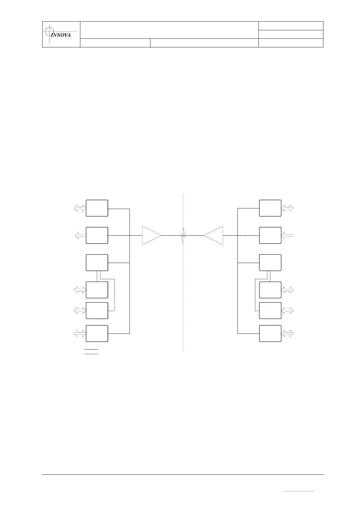
Figure 9 below shows a simple block diagram of the fibre optic multiplexer system.
LINK
Ethernet
LINK
Dig.Video
WDM
LINK
AV
Matrix
Serial #1
Matrix
Serial #2
WDM
LINK
Ethernet
LINK
Dig.Video
LINK
AV
Matrix
Serial #1
Matrix
Serial #2
Fibre
Electric
TOPSIDE
SUBSEA
LINK
PECL
LINK
PECL
Figure 9 - LINK mux system
Power management is provided by embedded power distribution boards with software resettable
fuses. These communicate via a RS485 network, utilising one of the serial channels of the fibre
optic multiplexer to communicate with the topside control unit.
The topside control unit contains the topside multiplexer boards, and a single board computer
which communicates with the subsea power distribution boards via the RS485 channel in the
mux, and provides a graphical user interface for operating the system via the touch screen.
The GUI computer and power distribution boards operate independently of the fibre optic
multiplexer. The GUI computer is mounted directly on the back of the front panel, and provides
both the touch screen GUI, and the web interface accessible over Ethernet via either the wireless
Ethernet connection or the Config Port.