3.2. Default Switch and Jumper Settings
This topic shows you how to restore the default factory settings and explains their
functions.
Caution: Do not install or remove jumpers (shunts) while the development board is powered
on.
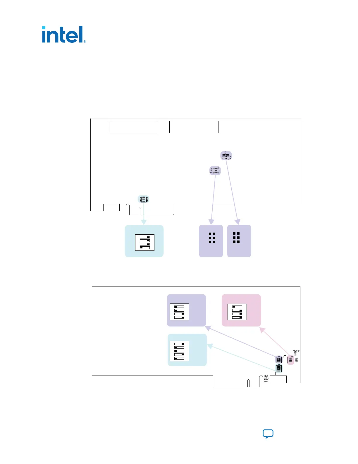
Figure 5. Default Switch and Jumper Settings on the Top
FMCBFMCA
SW3
PRSNTn
ON
4 3 2 1
X1
X4
X8
FMCB
VCCIO
1.8V
1.5V
1.35V
FMCA
J11 J8
Note for J11 & J 8:
No shunt = 1.2V
1.35V
1.5V
1.8V
Figure 6. Default Switch Settings on the Bottom
SW5
ON
1 2 3 4
MSEL0
MSEL1
MSEL2
VIDEN
SW4
CLK_SEL
CLK_EN
Si516_FS
FACTORY
RZQ_B2K
ON
1
1 0 1 0
2 3 4
ARRIA 10
MAX V
FMCA
FMCB
SW6
ON
1 2 3 4 5
1. Set DIP switch bank (SW3) to match the following table.
3. Development Board Setup
683526 | 2023.07.12
Intel
®
Arria
®
10 FPGA Development Kit User Guide
Send Feedback
12