4.4.11. The Power Monitor
The Power Monitor measures and reports current power information and
communicates with the MAX V device on the board through the JTAG bus. A power
monitor circuit attached to the MAX V device allows you to measure the power that
the FPGA is consuming.
To start the application, click the Power Monitor icon in the Board Test System
application. You can also run the Power Monitor as a stand-alone application. The
PowerMonitor.exe resides in the <package dir>\examples
\board_test_system directory.
Note: You cannot run the stand-alone power application and the BTS application at the same
time. Also, you cannot run power and clock interface at the same time
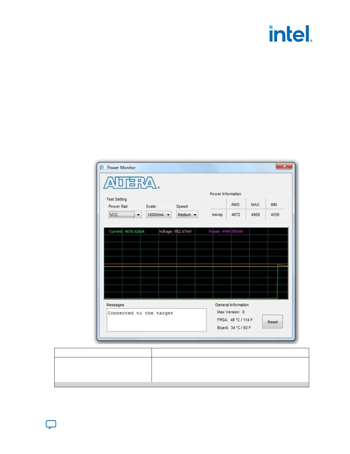
Figure 26. Power Monitor Interface
Control Description
Test Settings Displays the following controls:
Power Rail—Indicates the currently-selected power rail. After selecting
the desired rail, click Reset to refresh the screen with updated board
readings.
continued...
4. Board Test System
683526 | 2023.07.12
Send Feedback
Intel
®
Arria
®
10 FPGA Development Kit User Guide
47