6.5. User Input/Output
6.5.1. User-Defined Push Buttons
The Arria 10 GX FPGA development board includes user-defined push buttons. When
you press and hold down the button, the device pin is set to logic 0; when you release
the button, the device pin is set to logic 1. There are no board-specific functions for
these general user push buttons.
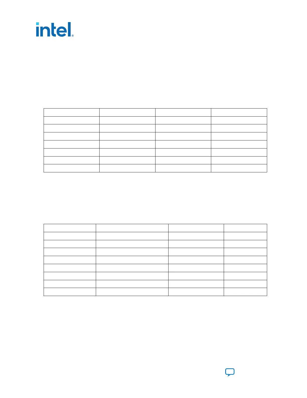
Table 18. User-Defined Push Button Schematic Signal Names and Functions
Board Reference Schematic Signal Name FPGA Pin Number I/O Standard
S1 USER_PB2 U11 1.8 V
S2 USER_PB1 U12 1.8 V
S3 USER_PB0 T12 1.8 V
S4 CPU_RESETn BD27 1.8 V
S5 PGM_SEL — 2.5 V
S6 PGM_CONFIG — 2.5 V
S7 MAX_RESETn — 2.5 V
6.5.2. User-Defined DIP Switch
The Arria 10 GX FPGA development board includes a set of eight-pin DIP switch. There
are no board-specific functions for these switches. When the switch is in the OFF
position, a logic 1 is selected. When the switch is in the ON position, a logic 0 is
selected.
Table 19. User-Defined DIP Switch Schematic Signal Names and Functions
Board Reference Schematic Signal Name FPGA Pin Number I/O Standard
1 USER_DIPSW0 A24 1.8-V
2 USER_DIPSW1 B23 1.8-V
3 USER_DIPSW2 A23 1.8-V
4 USER_DIPSW3 B22 1.8-V
5 USER_DIPSW4 A22 1.8-V
6 USER_DIPSW5 B21 1.8-V
7 USER_DIPSW6 C21 1.8-V
8 USER_DIPSW7 A20 1.8-V
6.5.3. User-Defined LEDs
The Arria 10 GX FPGA development board includes a set of eight pairs user-defined
LEDs. The LEDs illuminate when a logic 0 is driven, and turns off when a logic 1 is
driven. There are no board-specific functions for these LEDs.
6. Board Components
683526 | 2023.07.12
Intel
®
Arria
®
10 FPGA Development Kit User Guide
Send Feedback
68