4.4.2. The System Info Tab
The System Info tab shows the board’s current configuration. The tab displays the
contents of the MAX V registers, the JTAG chain, the board’s MAC address, the Qsys
memory map, and other details stored on the board.
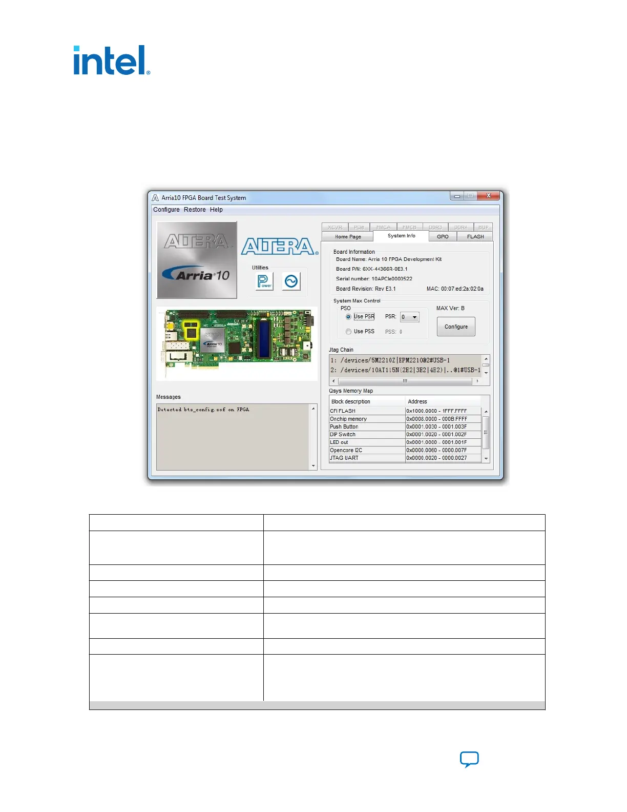
Figure 16. The System Info Tab
Table 13. Controls on the System Info Tab
Controls Description
Board Information Controls The board information is updated once the GPIO design is configured.
Otherwise, this control displays the default static information about your
board.
Board Name Indicates the official name of the board, given by the Board Test System.
Board P/N Indicates the part number of the board.
Serial Number Indicates the serial number of the board.
Factory Test Version Indicates the version of the Board Test System currently running on the
board.
MAC Indicates the MAC address of the board.
MAX V Control Allows you to view and change the current register values, which take
effect immediately:
System Reset (SRST) — Write only. Click to reset the FPGA.
Page Select Override (PSO) — Read/Write
continued...
4. Board Test System
683526 | 2023.07.12
Intel
®
Arria
®
10 FPGA Development Kit User Guide
Send Feedback
26