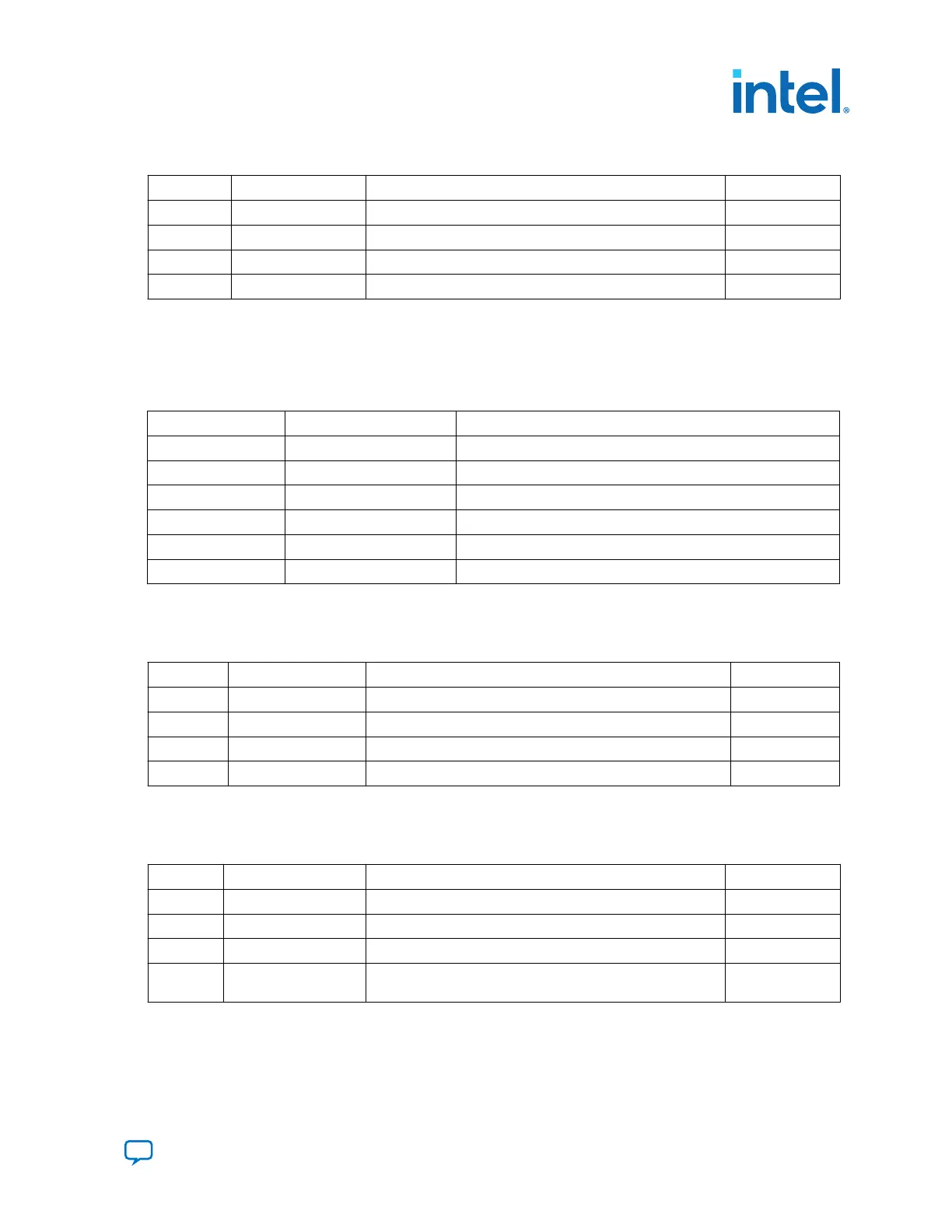
Table 2. SW3 DIP PCIe Switch Default Settings (Board Top)
Switch Board Label Function Default Position
1 x1 ON for PCIe x1 ON
2 x4 ON for PCIe x4 ON
3 x8 ON for PCIe x8 ON
4 — OFF for 1.35 V MEM_VDD power rail OFF
2. If all of the jumper blocks are open, the FMCA and FMCB VCCIO value is 1.2 V. To
change that value, add shunts as shown in the following table.
Table 3. Default Jumper Settings for the FPGA Mezzanine Card (FMC) Ports (Board
Top)
Board Reference Board Label Description
J8 pins 1-2 1.35V 1.35 V FMCB V
CCIO
select
J8 pins 3-4 1.5V 1.5 V FMCB V
CCIO
select
J8 pins 5-6 1.8V 1.8 V FMCB V
CCIO
select
J11 pins 1-2 1.35V 1.35 V FMCA V
CCIO
select
J11 pins 3-4 1.5V 1.5 V FMCA V
CCIO
select
J11 pins 5-6 1.8V 1.8 V FMCA V
CCIO
select
3. Set DIP switch bank (SW4) to match the following table.
Table 4. SW4 JTAG DIP Switch Default Settings (Board Bottom)
Switch Board Label Function Default Position
1 ARRIA 10 OFF to enable the Arria 10 in the JTAG chain OFF
2 MAX V OFF to enable the MAX V in the JTAG chain OFF
3 FMCA ON to bypass the FMCA connector in the JTAG chain ON
4 FMCB ON to bypass the FMCB connector in the JTAG chain ON
4. Set DIP switch bank (SW5) to match the following table.
Table 5. SW5 DIP Switch Default Settings (Board Bottom)
Switch Board Label Function Default Position
1 MSEL0 OFF for MSEL0 = 1; for FPP standard mode OFF
2 MSEL1 ON for MSEL1 = 0; for FPP standard mode ON
3 MSEL2 ON for MSEL2 = 0; for FPP standard mode ON
4 VIDEN
OFF for enabling VID_EN for the Smart Voltage ID (SmartVID)
feature
ON
5. Set DIP switch bank (SW6) to match the following table.
3. Development Board Setup
683526 | 2023.07.12
Send Feedback
Intel
®
Arria
®
10 FPGA Development Kit User Guide
13