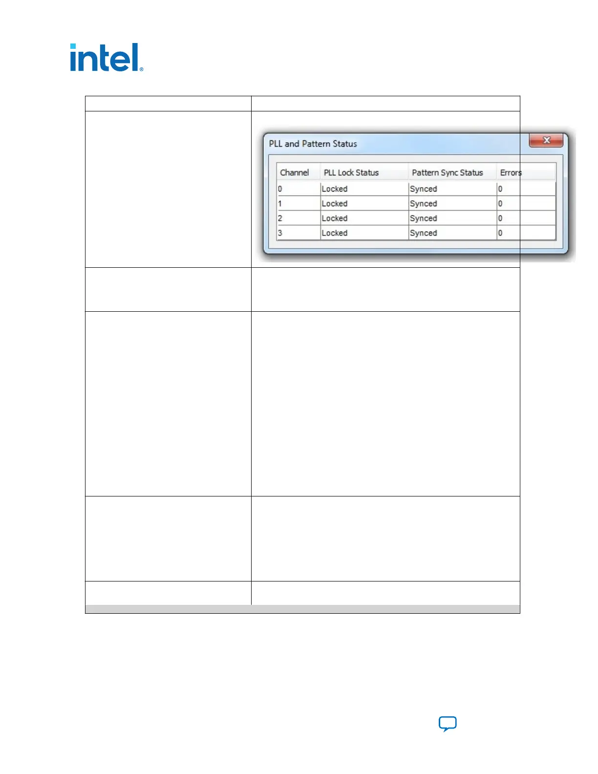
Control Description
Details—Shows the PLL lock and pattern sync status:
Port Allows you to specify which interface to test. The following port tests are
available:
XCVR
CMOS
PMA Setting Allows you to make changes to the PMA parameters that affect the active
transceiver interface. The following settings are available for analysis:
Serial Loopback—Routes signals between the transmitter and the receiver.
VOD—Specifies the voltage output differential of the transmitter buffer.
Pre-emphasis tap
• 1st pre—Specifies the amount of pre-emphasis on the pre-tap of the
transmitter buffer.
• 2nd pre—Specifies the amount of pre-emphasis on the second pre-tap
of the transmitter buffer.
• 1st post—Specifies the amount of pre-emphasis on the first post tap of
the transmitter buffer.
• 2nd post—Specifies the amount of pre-emphasis on the second post
tap of the transmitter buffer.
Equalizer—Specifies the AC gain setting for the receiver equalizer in four
stage mode.
DC gain—Specifies the DC gain setting for the receiver equalizer in four
stage mode.
VGA—Specifies the VGA gain value.
All PMA settings should be changed as in Figure 20 on page 33.
Data Type Specifies the type of data contained in the transactions. The following data
types are available for analysis:
• PRBS 7—Selects pseudo-random 7-bit sequences.
• PRBS 15—Selects pseudo-random 15-bit sequences.
• PRBS 23—Selects pseudo-random 23-bit sequences.
• PRBS 31—Selects pseudo-random 31-bit sequences.
• HF—Selects highest frequency divide-by-2 data pattern 10101010.
• LF—Selects lowest frequency divide by 33 data pattern.
Error Control Displays data errors detected during analysis and allows you to insert
errors:
continued...
4. Board Test System
683526 | 2023.07.12
Intel
®
Arria
®
10 FPGA Development Kit User Guide
Send Feedback
38

 Loading...


