USER MANUAL
INTEL® FALCON™ 8+ UAS
© 2017 Intel Corporation. All rights reserved 25
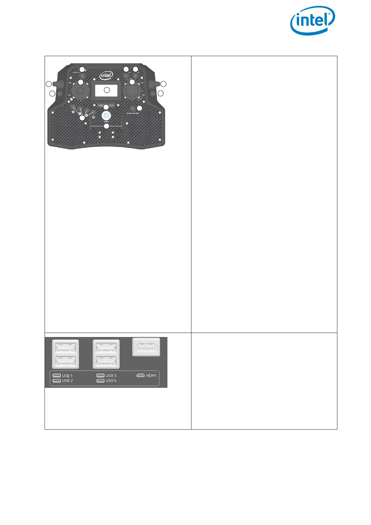
The functional elements of the CTR
remote control unit are:
(1) START/STOP button: starts/stops the
motors when the left stick is
simultaneously held down (see
“STARTING AND STOPPING THE
MOTORS” on page 101).
(2) GPS button: GPS-Mode ON
(3) HGT button: Height-Mode ON. When
both buttons are switched ON/lit
Manual-Mode is activated
(4) Left rocker switch (R1) controls the
camera pitch angle, right rocker
switch (R2), controls different camera
functions depending on the attached
payload
(5) Left and right control sticks
(6) Status Display (see “STATUS
DISPLAY” on page 138).
(7) Left push button (B1) sets the camera
to predefined angles +/- 90°, +/- 45°
and 0° when the left rocker switch R1
(4) is pushed simultaneously, right
push button (B2) controls different
camera functions depending on the
attached payload
(8) Four function buttons for the Status
Display
(9) RETURN TO HOME button
(10)POWER button
(11)Integrated shoulder harness holders
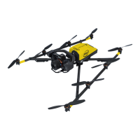
There are different connectors on the
back of the CTR:
4 X USB
1 X HDMI
The USB port labeled USB 1 can only be
used to perform firmware updates from a
USB stick. The other USB ports can be
used to connect the Independent Cam-
era Control (ICC) or USB sticks with pre-
planned flight missions.
Figure 2.7: Intel® Cockpit Controller (CTR) Overview (Continued)