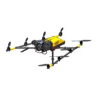
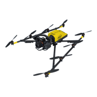
USER MANUAL
INTEL® FALCON™ 8+ UAS
© 2017 Intel Corporation. All rights reserved 47
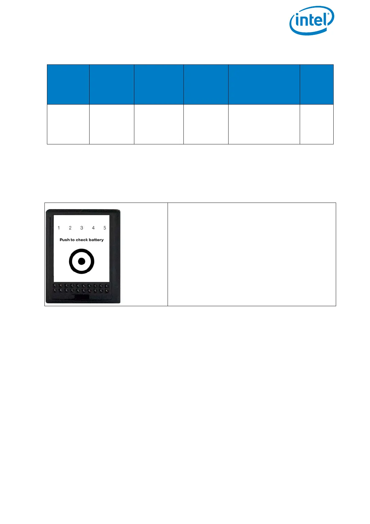
On the front panel of the battery there is a sticker. An area is marked by a dot
surrounded by a circle (see next figure The Intel® Powerpack Battery. This area has the
function of a button.
Please note the limitations mentioned on the labels of the Intel® Powerpack Battery.
Table 2.3: Technical Specifications of the Battery
BATTERY
TYPES
ELECTRIC
CHARGE
[MAH]
VOLTAGE
STANDARD
[V]
VOLTAGE
FULLY
CHARGED
[V]
VOLTAGE
LOWEST
RECOMMENDED
(UNDER LOAD) [V]
NO. OF
CELLS
Intel®
Power-
pack™
Battery
4000 14.8 16.8 14.0 4
Figure 2.20: LED Description
Led Description
The LEDs are integrated in the front panel of
the battery.
LED number / color from left to right:
•1 / red
•2 / yellow
• 3 / green
• 4 / green
• 5 / green