SERVICE MANUAL
Invacare
®
- Bora/Spectra XTR
24
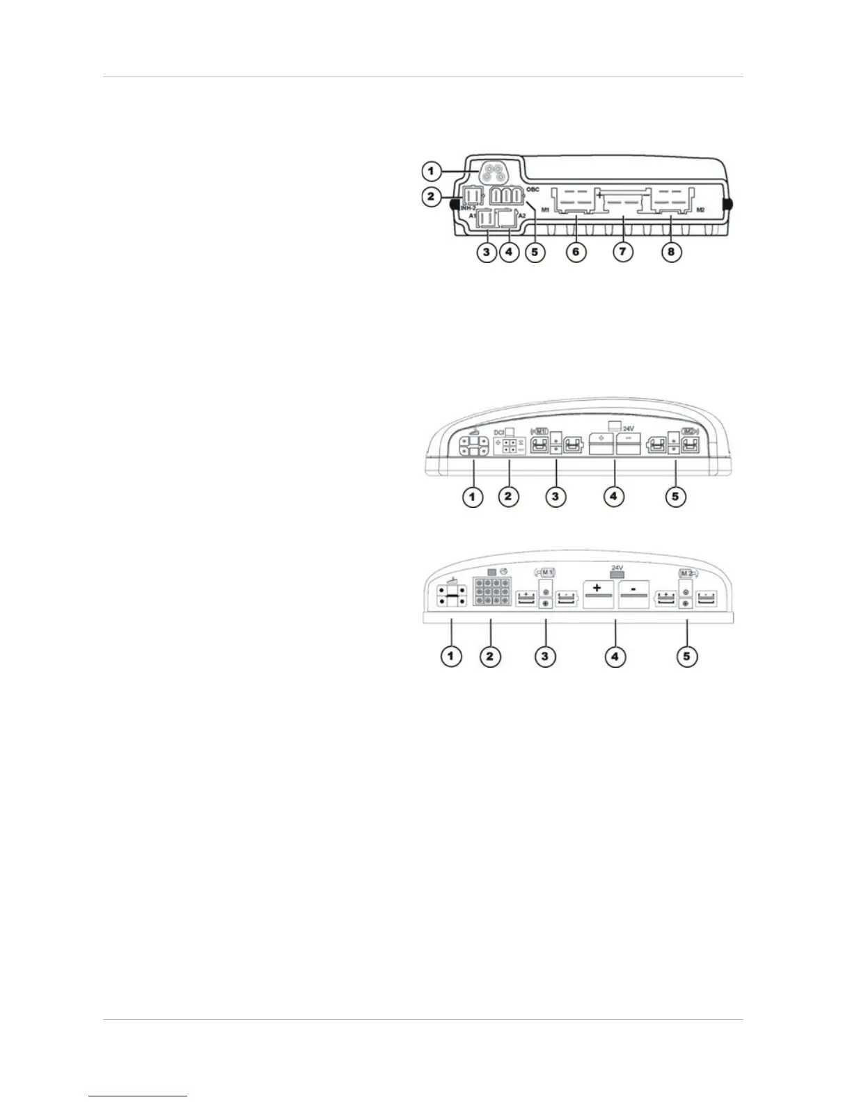
4.2.5 R-Net electronics module
Connections
1) Bus
2) Lock (INHIBIT 2)
3) Actuator 1
4) Actuator 2
5) On-board battery charger
6) Motor M1
7) Battery 24V
4.2.6 Shark electronics module
4.2.6.1 Shark with 4-pole DCI
BUS CA BLE
Connections
1) Joystick box
2) DCI for actuators (4-pole)
3) Right-hand motor M1
4) Battery 24V
5) Left-hand motor M2
4.2.6.2 Shark with DCI 12-pole
Connections
1) Cable to remote
2) DCI for actuators/lighting (12-pole)
3) Right-hand motor M1
4) Battery 24V
5) Left-hand motor M2
4.2.7 ACT actuator module
A range of adjusting motors, also known as actuators, can be fitted to the mobility device. These
actuators are either connected directly to the electronics module or to a separate actuator module.
The actuator module is connected with the electronics module via a bus cable.