26
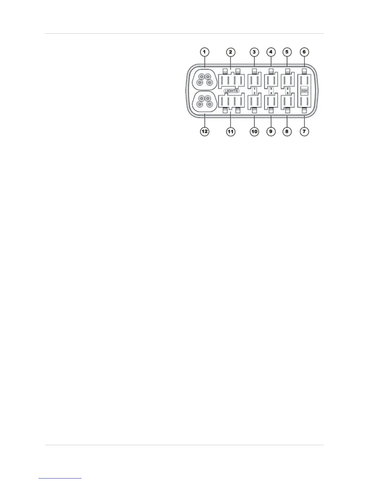
Connections
1) Bus cable (to remote or ACT)
2) Light left
3) Adjusting motor/actuator - Channel 1
4) Adjusting motor/actuator - Channel 3
5) Adjusting motor/actuator - Channel 5
6) INH 4*
7) INH 5*
8) Adjusting motor/actuator - Channel 6
9) Adjusting motor/actuator - Channel 4
10) Adjusting motor/actuator - Channel 2
11) Light right
12) Bus cable (to remote or ACT)
* The INH connection is used for actuator limitation or speed reduction.
4.2.9 Lighting PCB
The lighting PCB connections are printed on the circuit board itself.