190
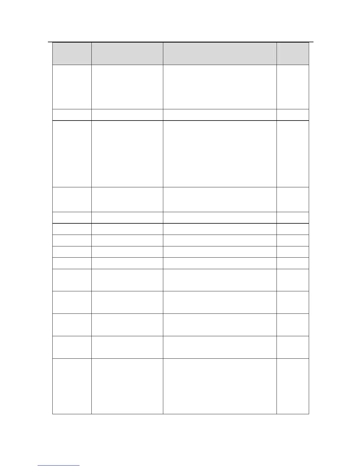
Function
code
Name Detailed instruction of parameters
Default
value
4:High speed pulse HDI set
5:Multi-step speed set
6:MODBUS communication
7~9:Reserved
P09.01 Keypad PID preset -100.0%~100.0% 0.0%
P09.02 PID feedback source
0:Analog channel AI1 feedback
1:Analog channel AI2 feedback
2:Analog channel AI3 feedback
3:High speed HDI feedback
4:MODBUS communication feedback
5~7:Reserved
0
P09.03 PID output feature
0:PID output is positive
1:PID output is negative
0
P09.04 Proportional gain (Kp) 0.00~100.00 1.00
P09.05 Integral time(Ti) 0.01~10.00s 0.10s
P09.06 Differential time(Td) 0.00~10.00s 0.00s
P09.07 Sampling cycle(T) 0.00~100.00s 0.10s
P09.08 PID control deviation limit
time
0.0~3600.0s 1.0s
P09.13 PID adjustment
LED ones:
0: Keep on integral adjustment when the
frequency achieves the upper and low
limit; the integration shows the change
between the reference and the feedback
0x0001
 Loading...