USER MANUAL
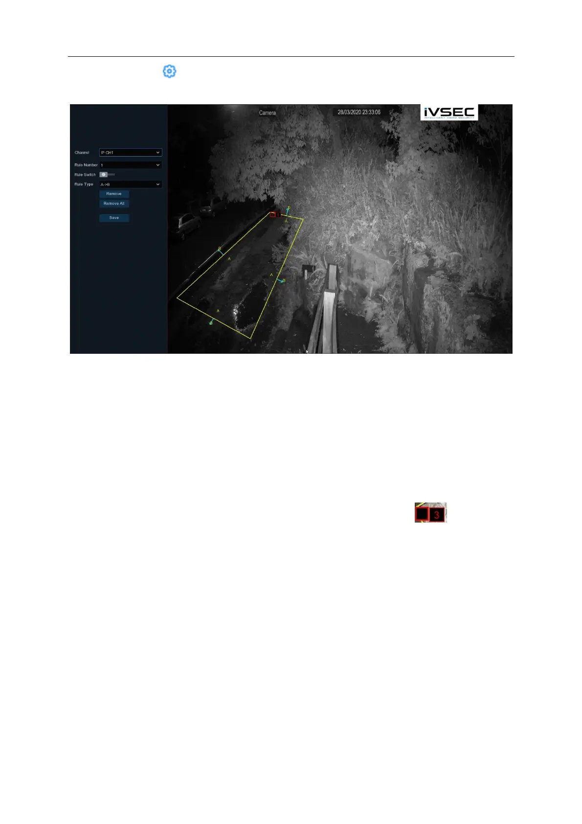
Setup: Click on the icon to draw the PID region. If this icon is greyed out or a camera is not
visible in the PID menu then it means that the camera does not support PID function
1. Choose one of the Rule Numbers. You can set a maximum of 4 PID areas.
2. enable the Rule Switch option to Enable detection.
3. Choose a Rule Type.
AB: Movement from inside the PID area to the outside.
BA: Movement from outside the PID area to the inside.
AB: Movement in either direction.
4. Use your mouse to click 4 points in the camera picture to draw a virtual region. The shape of
the region should be a convex polygon. Concave polygons cannot be saved.
5. Click Save to save your settings.
6. If you want to modify the position or sharp of region, click the red box in the region,
the borders of the region will be changed to red colour. Long press the left button of your
mouse to move the position of the region, or drag the corners to resize the region.
7. If you want to remove one of the regions from the camera picture, click the red box in the
region and then click Remove button. Click Remove All will delete all regions.
8. To exit out of the current menu click on the right mouse button
Notice:
1) The perimeter must not be too close to the edges/corners of the camera picture, since it may
fail to trigger the detection when the target passes through the edges/corners.
2) The shape of the regions must not be too narrow/small, since it may fail to trigger the detection
when the target passes through outside the perimeter.