9
9
1
2
10
7-2. Connector
7-2-1. Interface Connector
X4:Serial(ID-003)/MDB/Pulse/ccTalk Specification
The following diagram is the interface connector as viewed from the acceptor side or from a
relay board.
Box Type Plug
XG4C-1034 (Omron)
- If a relay board is attached to the TAIKO unit, do not attempt to re-
move it.
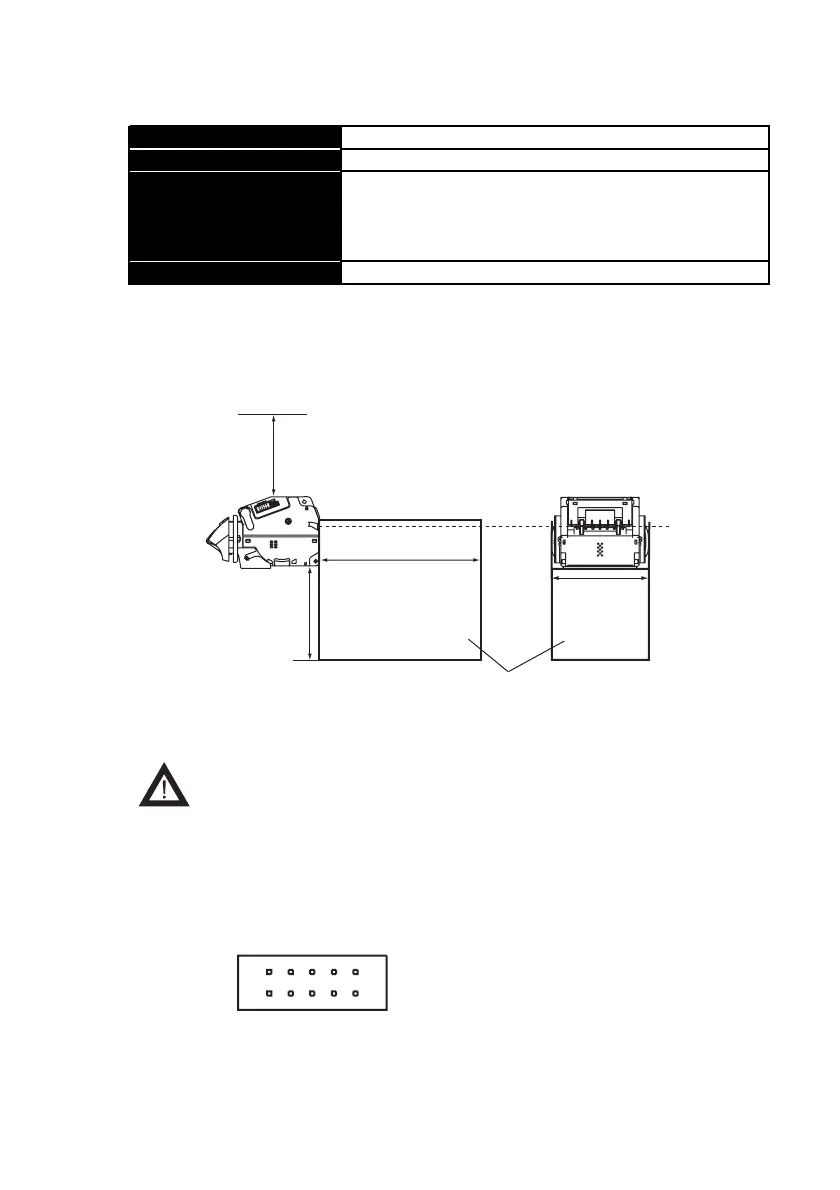
7-1-4. Installation Specifications
Mounting *1 Door and Horizontal Mounting (No vibration)
Weight Approx. 0.6 kg
External Dimensions
When installing Type 1/2/3 faceplate:
124mm (W) x 88mm (H) x 145.2mm (D)
When installing Type 5 faceplate:
124mm (W) x 88mm (H) x 143mm(D)
Cashbox *2 Supplied by the customer
*1 Allow 100 mm above the unit to open the lid for removal of the unit from the
faceplate
*2 The cashbox must be 100 mm or more in depth from the bottom of the TAIKO
unit, 200 mm or more in depth from the rear of the unit and 100 mm or more in
width. Both sides of the cashbox must be higher than the position of the bill
ejection slot.
Depth from rear of unit
200 mm or more
Cashbox
100 mm or more
Depth from bottom of unit
100 mm or more
Width
100 mm or more
Position of
bill ejection slo
Side
Rear