11
Pulse Communication
Pin No. Signal Name I/O *1 Function
1 NC - Not Connected
2 NC - Not Connected
3
ENABLE/
DISABLE (-)
4
ENABLE/
DISABLE (+)
5 VEND(-)
6VEND(+)
7 VCC - 12V DC Power Supply
8 VSS - Power Supply GND
9 NC - Not Connected
10 NC - Not Connected
IN
OUT
Enable/Disable Signal Input Line
(Enable when the current is applied.
Disable when the current is NOT
applied.)
Pulse Signal Output Line
(Active when the current is applied.)
*1 Conditions for the I/O (Input/Output) column are from the acceptor side.
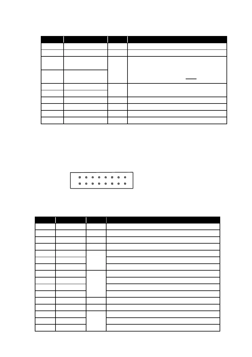
7-2-2. Interface Connector
01:Parallel(ID-001) Specification
The following diagram is the interface connector as viewed from the acceptor side or from a
relay board.
16PIN Connector
S16B-PADSS-1 (JST)
7-2-2-1.Interface Connector Pin Assignment
01:Parallel(ID-001) Specification
Pin No. Signal Name I/O *1 Function
1VCC-12V DC Power Supply
2VCC-12V DC Power Supply
3 VSS - Power Supply GND
4 NC - Not Connected
5 ACK ACK Receive Line
6 REJ REJ Receive Line
7 INH INH Receive Line
8 VALID VALID Send Line
9 VEND1 VEND1 Send Line
10 VEND2 VEND2 Send Line
11 VEND3 VEND3 Send Line
12 NC - Not Connected
13 NC - Not Connected
1 4 BU SY BU SY Se n d L in e
15 ABN ABN Send Line
16 STKF STKF Send Line
IN
OUT
OUT
*1 Conditions for the I/O (Input/Output) column are from the acceptor side.