4-3
TAIKO Service Manual
CHAPTER
4
© 2006 Japan Cash Machine Co.Ltd. All rights reserved.
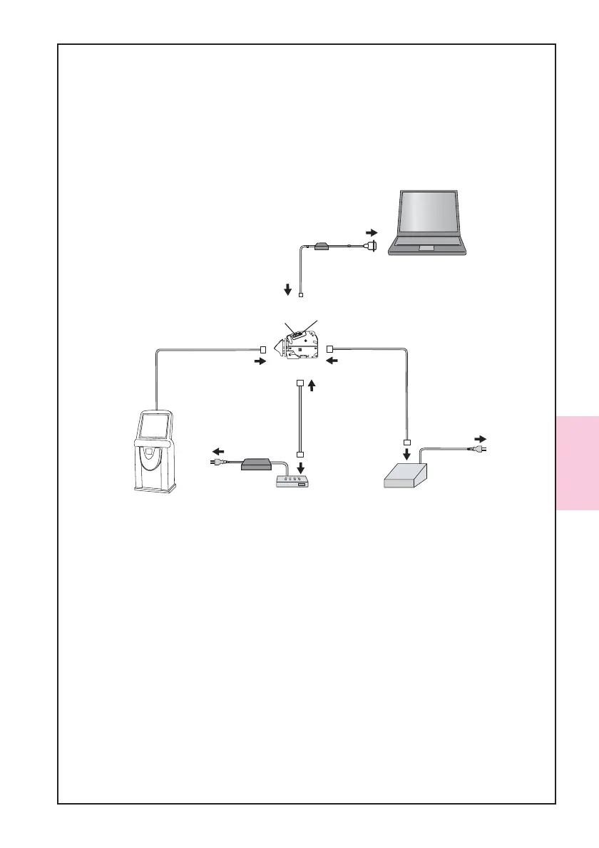
4-1-2. Connecting Procedure
1. Set the DIP switch No.1, 7 and 8. DIP switch is located on the right side of TAIKO
Unit.
2. Connect the tool (the TAIKO Unit, PC, and the Power Supply Unit) and a harness as
the following illustration indicates. Be sure that the TAIKO is connected to PC by
using the TAIKO Harness .
3. Turn the power of the JCM Power Supply Unit ON to turn on the power to the TAIKO
Unit.
4. Confirm the TAIKO’s green LED lamp is flashing.
A1:JCM Power Supply Unit
(Part#:VM-30, EDP#:116125)
or
equivalent
TAIKO Unit
AC Power
Serial
Port
TAIKO Adapter
EDP#:G00172
PC
(OS: Windows
(R)
98 SE/2000/XP)
A2:TAIKO Harness A
(Part#:3280-05-54,EDP#:127527)
Interface
Connector
Maintenance
Connector
Interface
Connector(10Pin)
Maintenance
Connector(4Pin)
Host Machine
ID-003/ccTalk/HII
Connector
ID-001
AC Power
B1:JCM Power Supply Unit
(Part#:VM-450, EDP#:059307)
or
equivalent
B2:VM-450 Connection Harness
(Part#:3280-05-102,EDP#:N/A)
ID-003/MDB/Pulse/ccTalk
ID-001
Connector
Interface
Connector
Without JCM Power Supply Unit
or
equivalent
A2:Harness A
EDP#:G00182 ID-0E3
EDP#:G00183 ID-003