TAIKO Service Manual
2-4
CHAPTER
2
© 2006 Japan Cash Machine Co., Ltd.. All rights reserved.
2-2. Connector
Pin No. Signal Name I/O *1 Function
1 ccTalk+ IN/OUT ccTalk Send/Receive Line
2 NC Not Connected
3 NC Not Connected
4 NC Not Connected
5 NC Not Connected
6 NC Not Connected
7 Vcc 12V DC Power Supply
8 Vss Power Supply GND
9 NC Not Connected
10 NC Not Connected
*1 Conditions for the I/O (Input/Output) column are from the Bill Acceptor side.
ccTalk Communication
Blue
Black
Box Type Plug XG4C-1034 (Omron)
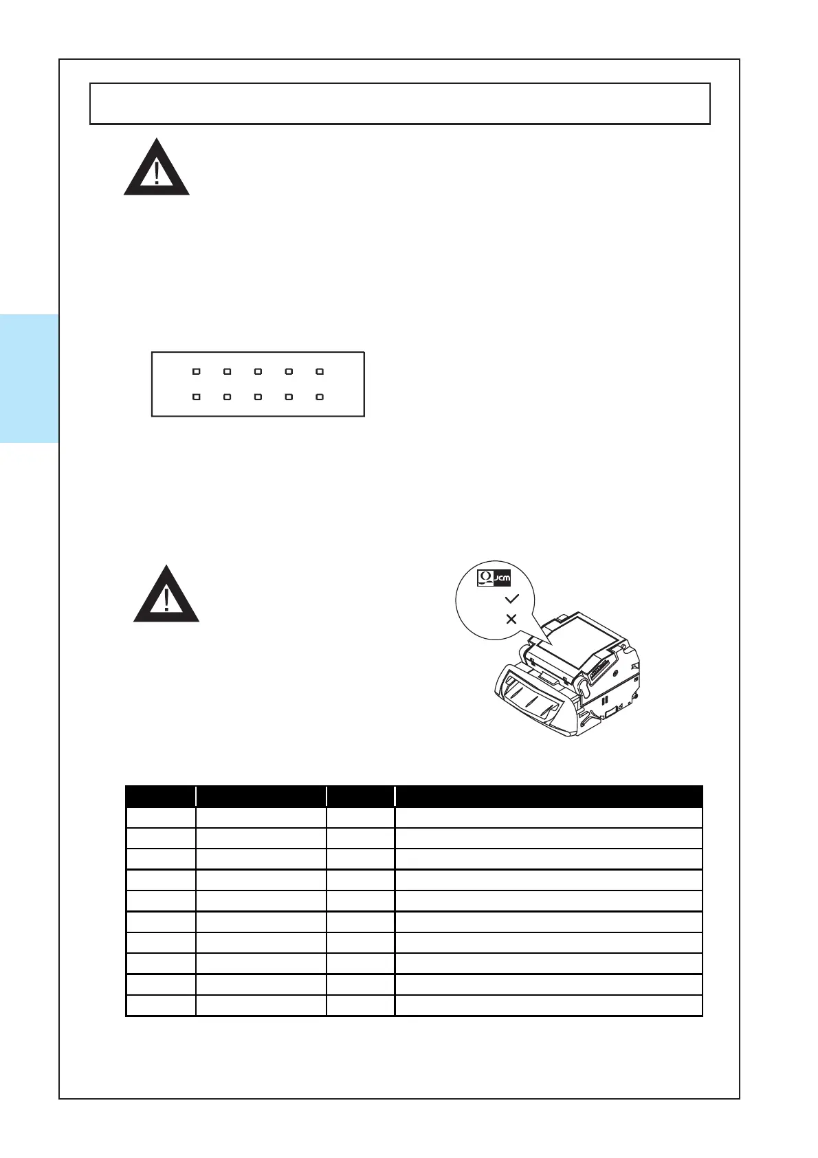
The following diagram is the interface connector as viewed
from the acceptor side or from a relay board.
- When a relay board has connected to the TAIKO unit, it was
fixed inside so do not r
emove from the TAIKO unit.
2-2-1. Interface Connector
X4: ID-003 (serial)/ MDB/ Pulse/ ccTalk Specification
2-2-1-1. Interface Connector Pin Assignments
X4: ID-003 (serial)/ MDB/ Pulse/ ccTalk Specification
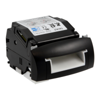
- The following pin assignment
is for TAIKO units with a
blue JCM logo label. If the
logois black, the pin assign-
ment may differ. For details,
contact JCM.