2-5
TAIKO Service Manual
© 2006 Japan Cash Machine Co., Ltd. All rights reserved.
CHAPTER
2
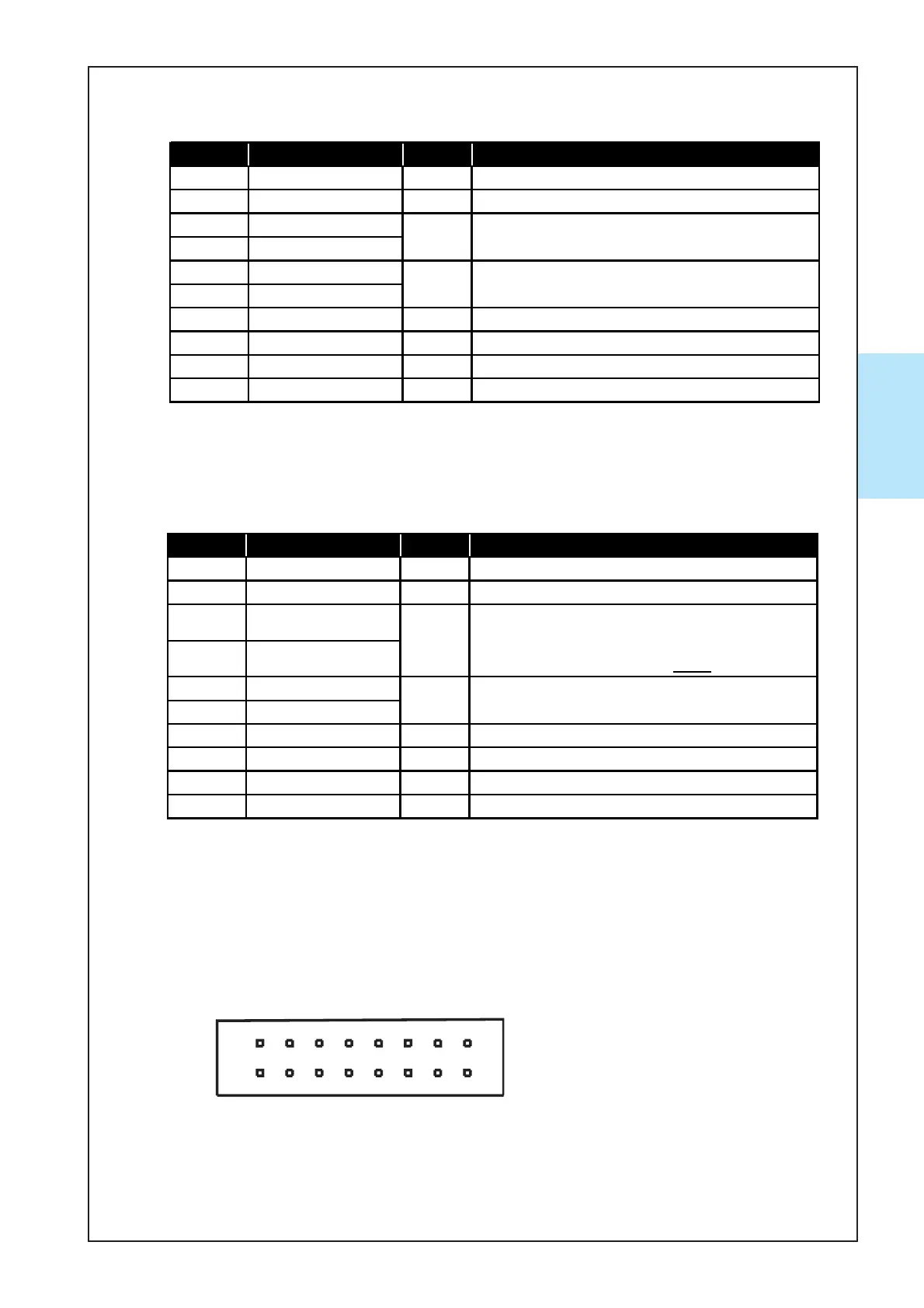
Pin No. Signal Name I/O *1 Function
1 NC - Not Connected
2 NC - Not Connected
3 RXD-
4 RXD+
5 TXD-
6 TXD+
7 Vcc - 12V DC Power Supply
8 Vss - Power Supply GND
9 NC - Not Connected
10 NC - Not Connected
IN
OUT
Data Send Line
(Active when the current is applied)
Data Receive Line
(Active when the current is applied)
*1 Conditions for the I/O (Input/Output) column are from the Bill Acceptor side.
ID-003 (serial)/ MDB Communication
Pin No. Signal Name I/O *1 Function
1 NC - Not Connected
2 NC - Not Connected
3Enable/Disable (-)
4Enable/Disable (+)
5Vend(-)
6Vend(+)
7 Vcc - 12V DC Power Supply
8 Vss - Power Supply GND
9 NC - Not Connected
10 NC - Not Connected
In
Out
Enable/Disable Signal Input Line
(Enable when the current is applied.
Disable when the current is NOT
applied.)
PULSE Signal Output Line
(Active when the current is applied.)
*1 Conditions for the I/O (Input/Output) column are from the Bill Acceptor side.
Pulse Communication
16
2
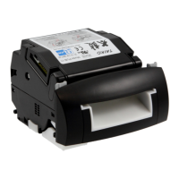
2-2-2. Interface Connector
01: ID-001 (parallel) Specification
The following diagram is the interface connector as viewed
from the acceptor side or from a relay board.
16PIN Connector S16B-PADSS-1(JST)