EasyManuals Logo

JRC JMA-9822-6XA User Manual

JRC JMA-9822-6XA
372 pages
To Next Page IconTo Next Page
To Previous Page IconTo Previous Page
Page #170 background imageLoading...
Page #170 background image
3 – 99
Procedures of Checking
q Read a current value A on the bar indicator.
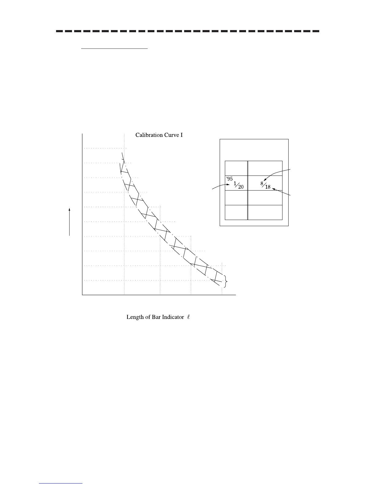
w Referring to the Calibration Curve I, obtain a relative attenuation d (B) for the initial bar
indicator length B that is specified in the INFORMATION LABEL.
e Then, obtain a relative attenuation d (A) for the value A referring to the Calibration Curve I.
The value given by d (A) - d (B) represents the attenuation of the current transmitted output
power compared with the value at the initial time.
r If the attenuation value given by d (A) - d (B) is 10 dB or more (due to the life of the
magnetron), it is necessary to request for checking the transmitter system by a service engineer.
Fig.1
PERF. MONITOR
INFORMATION LABEL
DATE
BAR LENGTH
0
2
4
6
8
10
12
14
16
18
20
22
097865342110
Relative Attenuation d
dB
Measuring
accuracy
Date and time of
initial setting
Initial bar
length
Maximum
range of
PM pattern

Table of Contents

Questions and Answers:

Question and Answer IconNeed help?

Do you have a question about the JRC JMA-9822-6XA and is the answer not in the manual?

JRC JMA-9822-6XA Specifications

General IconGeneral
BrandJRC
ModelJMA-9822-6XA
CategoryMarine Radar
LanguageEnglish

Related product manuals