8 – 17
As this radar equipment includes complicated circuits, it is necessary to request a specialist
engineer for repair or instructions for countermeasure if any circuit is defective.
There are also troubles by the following causes, which should be referred to in checking or
repair work.
1 Poor Contact in Terminal Board of Inter-Unit Cables
a) Poor contact in terminal board
b) The cable end is not fully treated, so that it is earthed or contacts with another terminal.
c) Disconnected cable wire
2 Poor Contact of Connector within Unit
Reference:
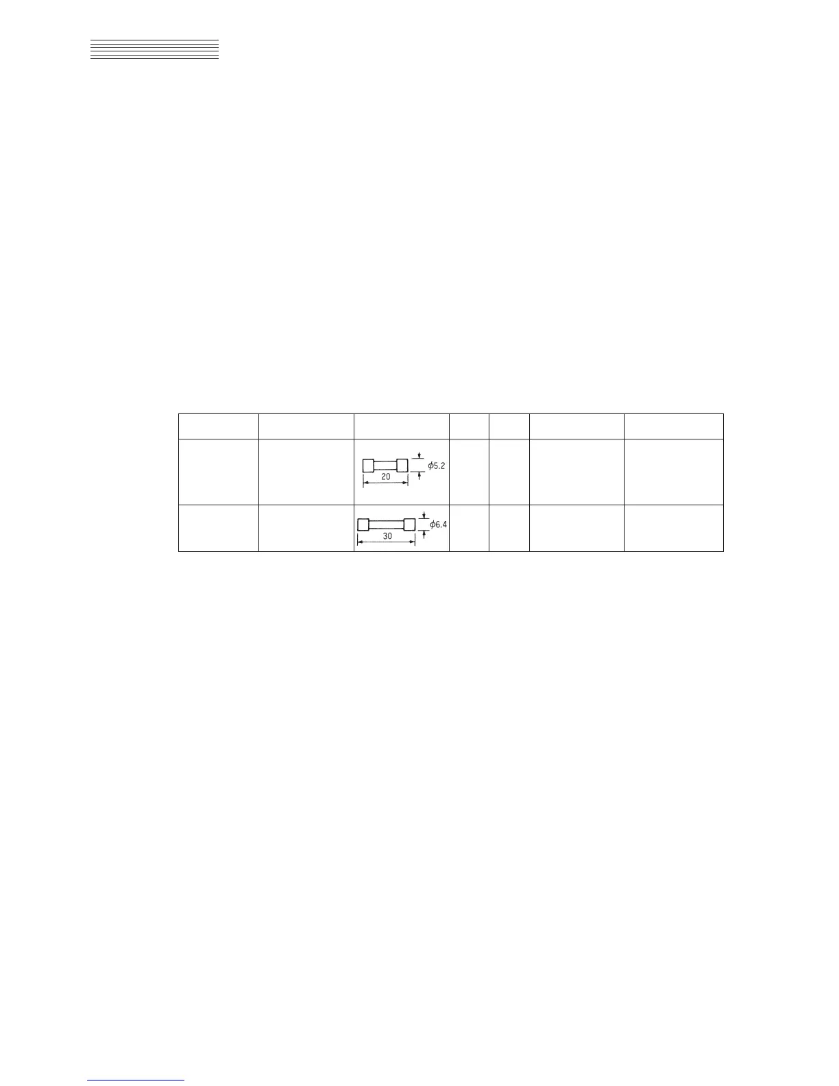
This radar equipment is provided with the standard spares as shown in Table 8.8.
Table 8.8 Spares (6ZXRD00198)
Name Type/Code Shape (mm) In use Spare Parts No. Location
MF51NN-1A
Transmitter-
Fuse
(5ZFAD00042)
13F1
receiver
PC1001
Fuse
MF60NR-0.5A
4 12 F1 to F4
Display
(5ZFAD00013) NSK Circuit
8.3
COUNTERMEASURES TO TROUBLE
 Loading...


