FX-3R Maintenance Guide
13-32
13-6. Z-θ Unit
The Z-θ unit is composed of an AC servo amplifier that drives the Z/θ-axes.
13-6-1. Structure of Z-θ Unit
In the AC servo amplifier for the Z-θ unit, one driver can drive 4 axes. Therefore, 3 drivers are
installed in FX-3.
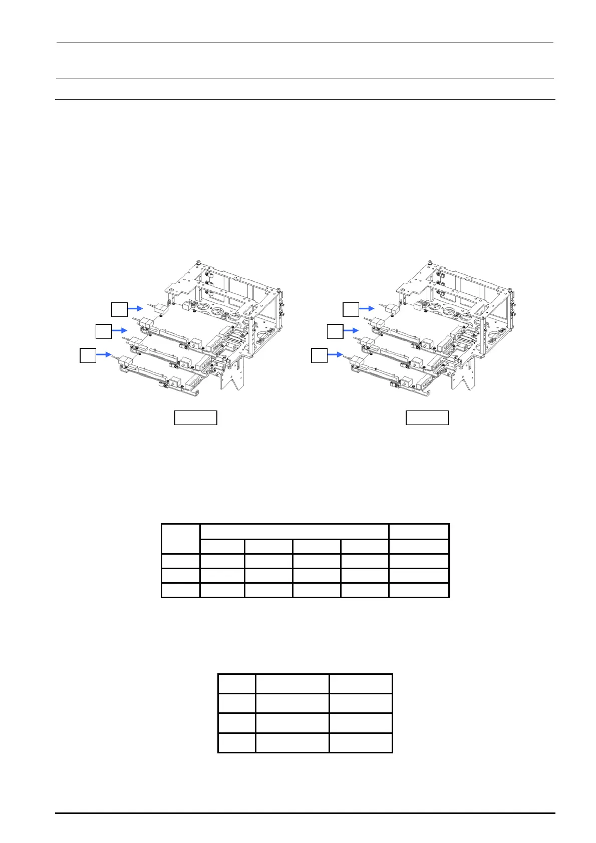
4-axis integrated type servo amplifier board for the Zθ-axis is mounted in the head unit. Actually,
three boards are mounted in the vertical direction.
Figure 13-6-1-1 shows the relationship among each motor and servo amplifier.
LF/RR
c
d
e
LR/RF
e
d
c
Figure 13-6-1-1 Structure of Z/θ Unit
∗ Motor outputs
Z-axis: 30W
θ-axis: 10W
Table 13-6-1-1 Z/θ-Unit Layout Relational Diagram
Axis No. on amplifier
Symbol
Axis No. 1 Axis No. 2
Axis No. 3
Axis No. 4
Part No.
c
L2 θ-axis L2 Z-axis
L1 θ-axis L1 Z-axis
40044535
d
L4 θ-axis L4 Z-axis
L3 θ-axis L3 Z-axis
40044535
e
L6 θ-axis L6 Z-axis
L5 θ-axis L5 Z-axis
40044535
For the Zθ-servo amplifier, set the rotary switch (CS1) appropriately according to the board.
Table 13-6-1-2 Z/θ-Unit Layout Relational Diagram
Symbol
Servo amplifier
SW set value
c
L1, 2 Z/θ-axis
1
d
L3, 4 Z/θ-axis
2
e
L5, 6 Z/θ-axis
3
Rev. 1.00