FX-3R Maintenance Guide
13-61
Rev. 1.00
13-11-2. FEEDER Board (40047560)
[Functions]
One board is arranged for each of the left and right stations, two boards in total.
c ATC open/close (WRITE) and its check sensor
d Feeder rise sensor, feeder detection sensor
e Bank up sensor is detected.
f CAL block LED is lit and vacuum is turned ON.
g Vacuum calibration sensor
h Feeder knock pin is driven.
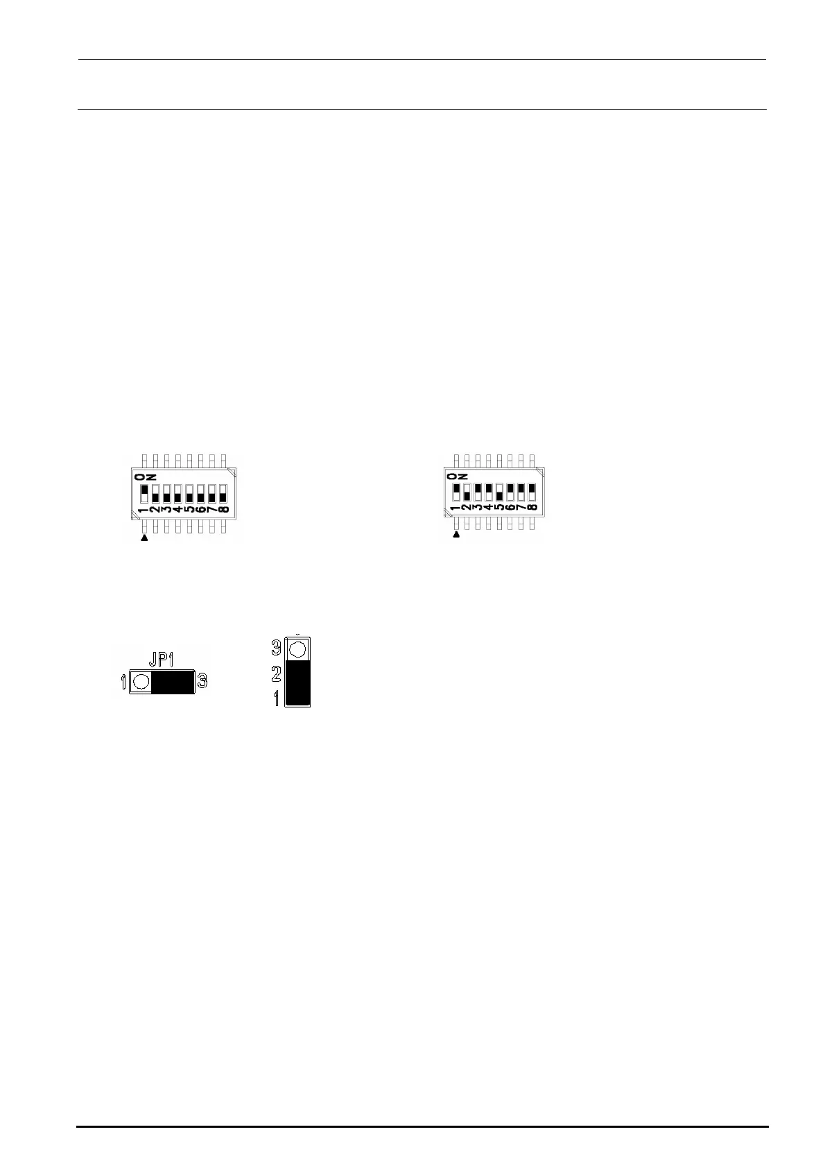
[Jumper switch settings]
portion shows the switch set position and receptacle mounting position.
DSW1 DSW2
[Adjustment items after replacement]
After that, follow the steps below to update the FLASH memory.
c Select [Options] and [Change User Group], and then select [Serviceman].
d Select [Maintenance] and [MS Parameter Setup].
e Select [Upgrade] and [Feeder].
f Clicking [Exec.] will start the upgrading process.
Jumper JP1 Jumper JP2 to 11
SW 2 [4..1]: Board function Rev.
SW 2 [8..5]: Board pattern Rev.
This switch has been set properly before shipment from
the factory. Therefore, do not change this switch setting.
The above Figure shows just an example.
No. 1: ON
No. 2 to 8: OFF

 Loading...


