FX-3R Maintenance Guide
13-44
Rev. 1.00
13-7-2. Adjusting the BASE-CARRY Board (40047559)
The jumper switches and DIP switches on the BASE-CARRY board assembly used in the transport
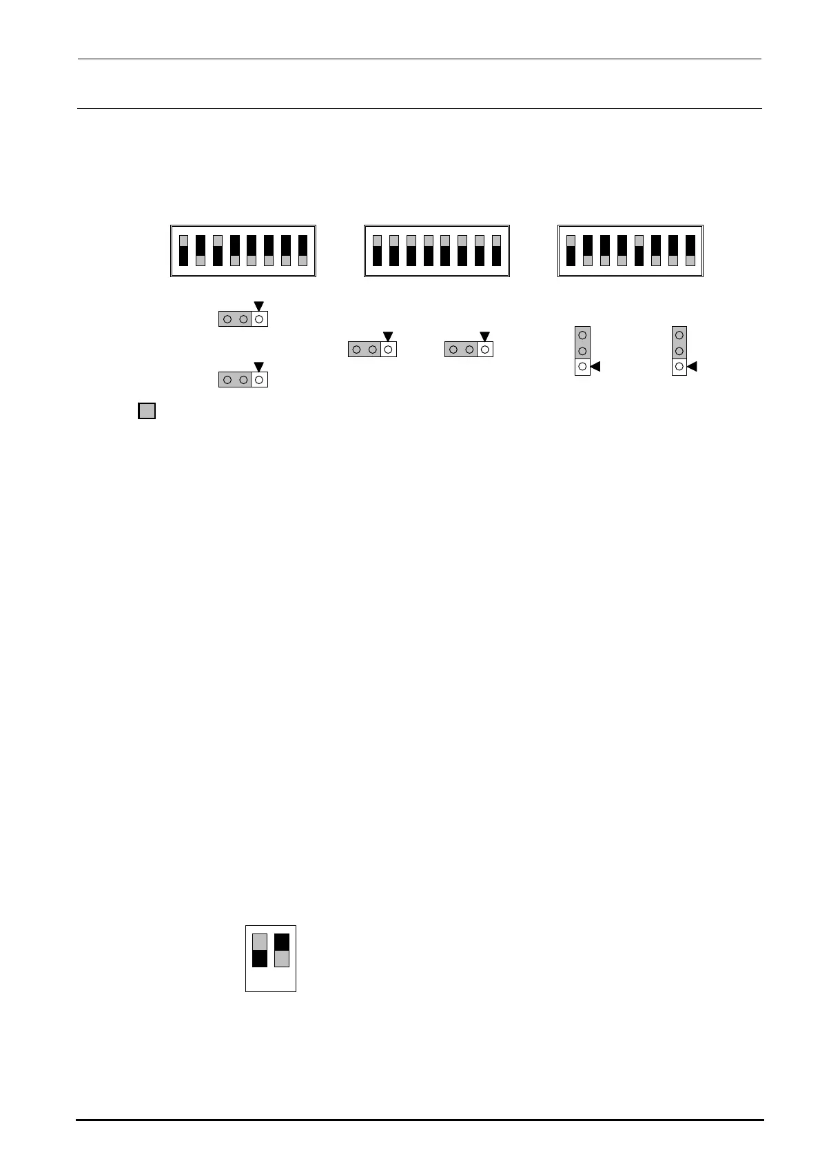
unit have already been set at delivery. However, check that they are set as shown below before
setting the BASE-CARRY board assembly in the transport unit.
Figure 13-7-2-1 DIP switches on BASE-CARRY Board Assembly
13-7-3. Adjusting the Stepping Driver
A stepping motor is used for the transport motor and support table/auto width adjustment motor of
the transport unit.
To rotate the stepping motor correctly, it is necessary to adjust the 5-phase stepping driver.
• IN, Center, OUT transport motor (Transport stepping motor)
HM001320000 5-phase stepping driver
• Support table/width adjustment motor (non-EN specification)
HX004200000 5-phase stepping driver
• Support table/width adjustment motor (EN specification)
HX005450000 5-phase stepping driver
13-7-3-1. Adjusting the Drive Current of the Transport Stepping Motor
<Adjustment Procedure>
c Before starting the adjustment procedure, make sure that the DC power source output
voltage has been properly adjusted.
(For details, see [10]-1, DC Power Source Output Voltage, in the QA table.)
d Turn the transport stepping motor and measure the voltage across [CP1] and [CP2] on the
five-phase stepping driver with a digital voltmeter.
Connect the positive (+) and negative (-) probes of the digital voltmeter to [CP1] and [CP2],
respectively.
e Slowly turn the RUN variable resistor so that the voltage across [CP1] and [CP2] becomes
2.8 ± 0.01 V.
f Set the DIP switches on the step driver as shown in the figure below.
Figure 13-7-3-1-1 DIP Switch Settings
• Specification value
Drive current: 1.4 A ± 0.005 A/phase
(Measured with the voltage across CP1 and CP2. 2.8 V ± 0.01 V)
部がスイッチの設定位置、及びリセ
タクルの取付位置となります。
1
2
3
4
5
6
7
8
SW3
1
2
3
4
5
6
7
8
SW2
1
2
3
4
5
6
7
8
SW4
W1
1
3
W2
1
3
1
3
W3
1
3
W4
3
1
W5
3
1
W6
portion shows the switch set position and receptacle mounting position.
ON
1 2
1.ON
2.OFF

 Loading...


