FX-3R Maintenance Guide
4-8
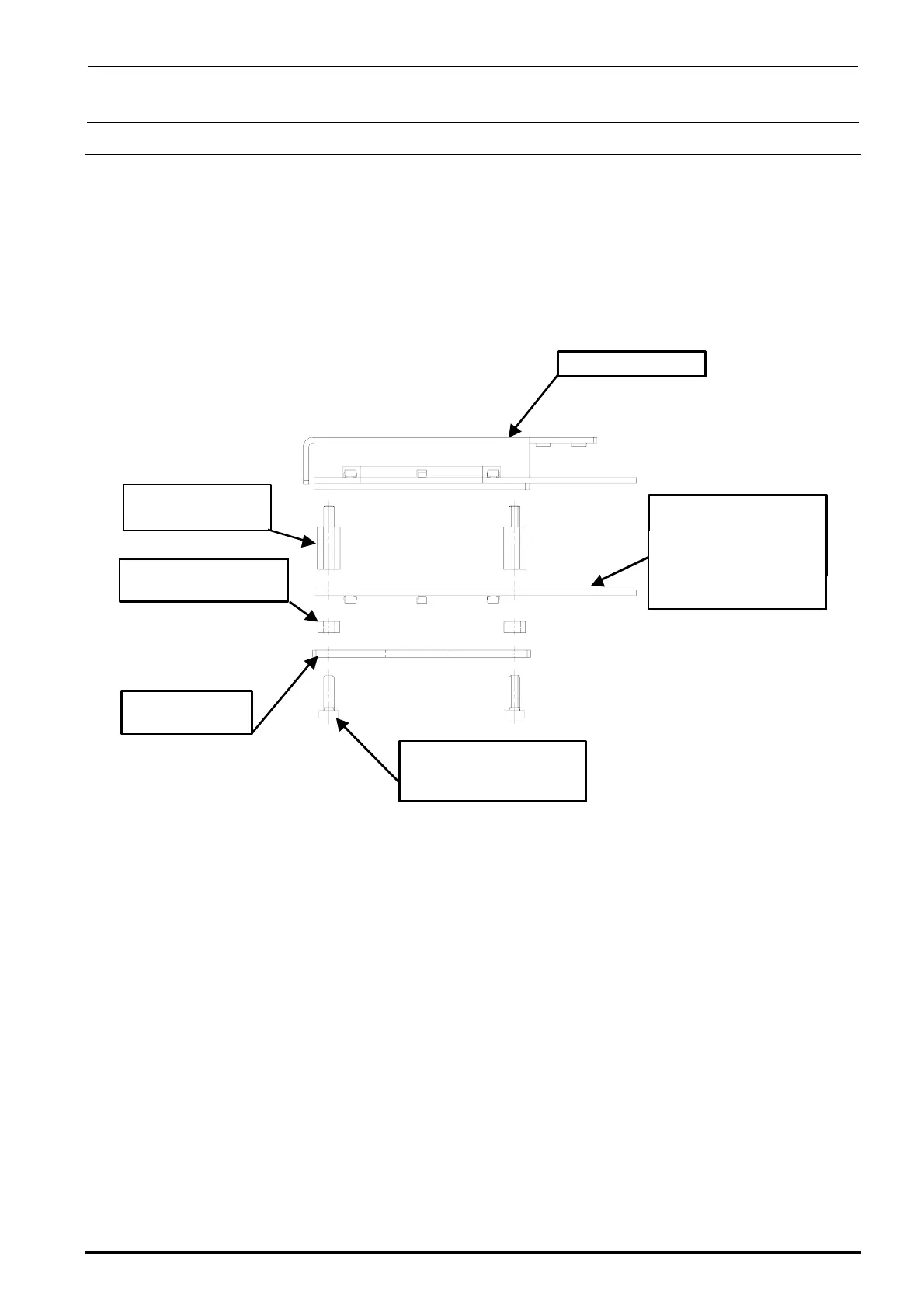
4-7. Replacing the Solder Recognition Light Board
<Procedure>
1) Remove the brazier head screws to detach the PRISM BASE, OCC angle light board, and
board spacers.
2) Reassemble the components in the reverse order of disassembly.
3) After the solder recognition light has been replaced, adjust the OCC light. (See 4-8, List of
Readjustment Items after Replacement.)
HX00335000G
基板スペーサ :4個
角度照明ユニット
HX00354000D
基板スタッド :4個
40032433
低頭ねじ M3×10 :4個
40014043
PRISM BASE
40047508
OCC A LIGHT PCB ASM
取付け向きに注意
(LED面下向き)
Angle light unit
Board stud: 4 pcs.
Board spacer: 4 pcs.
Carefully check the
mounting orientation.
(LED surface faces
downward.)
Brazier head screw
M3 × 10: 4 pcs.
Rev. 1.00