FX-3R Maintenance Guide
13-1
DANGER
To prevent any trouble caused by accidental machine start, always
shut-down the power before starting the maintenance and
adjustment work.
[13] ELECTRICAL COMPONENTS
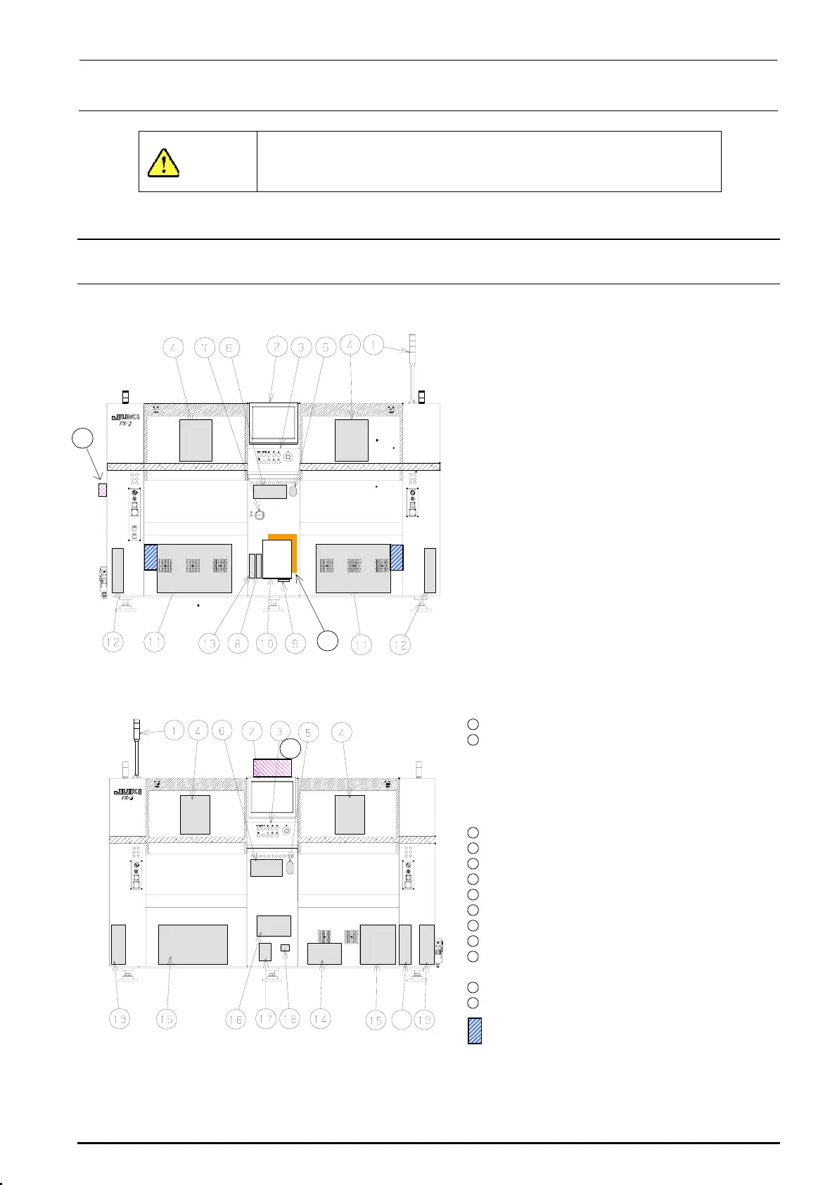
13-1. Layout of Electrical Components
Figure 13-1-1 shows the front view and Figure 13-1-2 shows the rear view.
c Signal tower
d LCD monitor
e Operation panel
Front: Operation board front assembly
Rear: Operation board rear assembly
(EN assembly for machines with EN
specifications)
f Head unit
21
Head main board assembly, Z/θ-servo
amplifier, HMS, OCC camera, OCC light
board
(OCC-A board assembly, OCC-C board
assembly),
Bad mark reader (Optional)
g Mouse
h Keyboard
i Power switch
j FDD
k SSD
l Control unit
Inside: CPU board, POSITION board,
IEEE1394A board, IP-X5 board,
CPCI back board
20
Figure 13-1-1 Front View
Outside: Superimpose board,
Mouse/keyboard change-over
board
11
XY-driver unit
12
Transport unit system electrical
components
5-phase stepping drivers (For transport
motor, auto PWB width adjustment, and
backup table), Base carry board assembly
(One board on right side only.)
22
13
DVD-ROM & CD-R/RW drive
14
Vacuum pump
15
Power supply unit
16
AC input unit L, AC input unit R
17
Circuit breaker
18
Hour meter
19
Feeder board assembly
20
ATX power supply
21
Barcode reader (Optional)
∗ To be installed on the transport IN side.
22
HUB-BOX (Optional)
23
XY-RELAY board assembly
23
portion Tester for CVS
Figure 13-1-2 Rear View
Rev. 1.00

 Loading...


